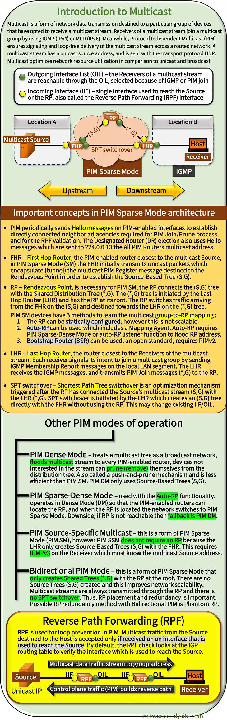
This blog post introduces the fundamental mechanisms underlying IP multicast including Layer-2 and Layer-3 multicast as well as basic device configurations for PIM Dense Mode and PIM Sparse Mode. Multicast is used in many aspects of computer networking both in the local subnetwork as well as in routed designs.
For example, OSPFv2 (and v3) and EIGRP protocol convergence rely on multicast used in local subnets (link-local multicast). The same is true for IPv6 SLAAC which uses the Neighbor Discovery Protocol (NDP) and relies on link-local multicast. Furthermore, VXLAN with Flood and Learn also relies on multicast over an IP routed network. The following infographic provides an overview of several related core topics.
Is multicast TCP or UDP?
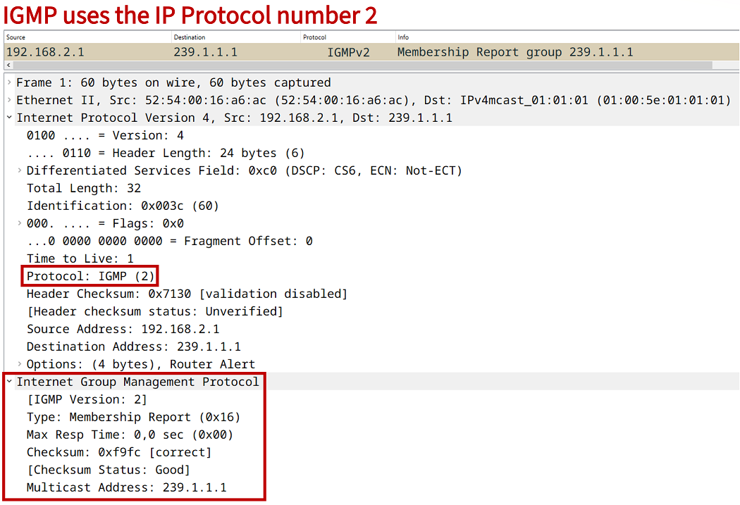
A multicast data stream is always sent with UDP as the transport protocol. However, multicast control plane traffic (PIM, IGMP and MLD) is neither TCP nor UDP, but instead has its own protocol number and is directly encapsulated in an IPv4 or IPv6 packet. For example, the following packet capture shows an IGMPv2 message which has the IP Protocol number 2.
Notice in the above capture the IP header and Ethernet header's destination address field. The multicast IPv4 address 239.1.1.1 is converted into the multicast MAC address 01:00:5e:01:01:01. MAC addresses that start with 01:00:5e always represent a multicast address.
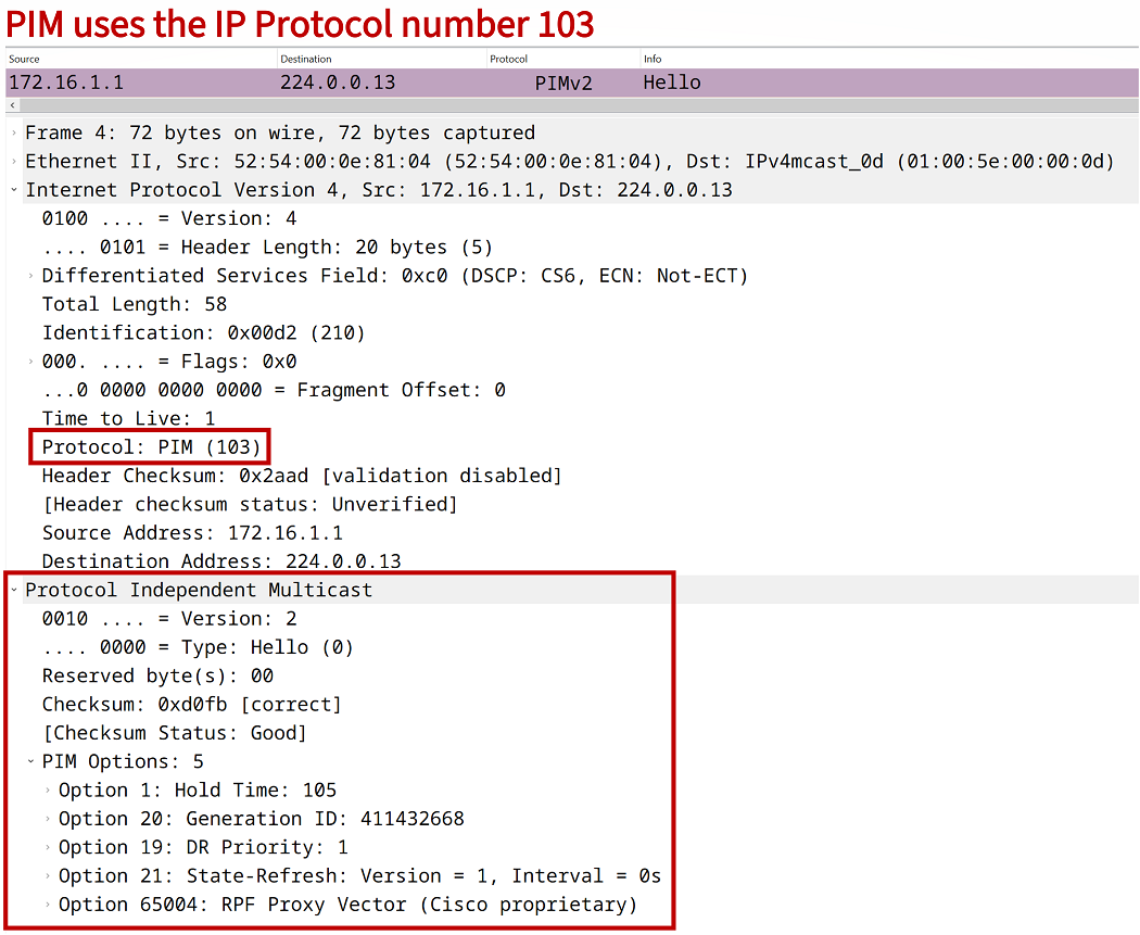
In the following packet capture a PIM message is displayed. Similar to IGMP, PIM is directly encapsulated in an IP packet and uses the IP Protocol number 103 also highlighted below. Notice that the destination of this PIM Hello message is the All PIM Routers multicast address 224.0.0.13 which is converted into a corresponding destination MAC address visible in the Ethernet header.
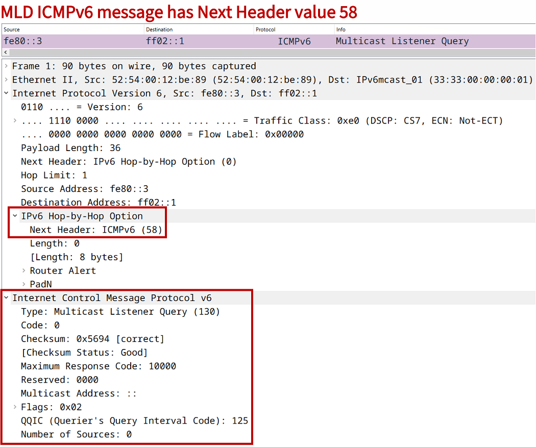
Multicast can also be configured with IPv6 which uses the Multicast Listener Discovery (MLD) mechanism to identify directly connected receivers (end hosts) that request a multicast stream. MLD in IPv6 replaces the function of IGMP in IPv4. MLD is described in RFC 2710 which includes the following quote. The subsequent packet capture displays an MLD Multicast Listener Query message.
MLD is a sub-protocol of ICMPv6, that is, MLD message types are a subset of the set of ICMPv6 messages, and MLD messages are identified in IPv6 packets by a preceding Next Header value of 58.
RFC 2710, Multicast Listener Discovery (MLD) for IPv6
Does IPv6 use multicast?
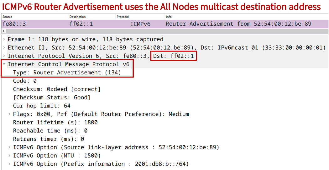
Yes, IPv6 uses multicast. The multicast IPv6 address range is FF00::/8 and a corresponding MAC address has its first two octets fixed at the values 33:33 as seen in the above MLD packet capture. In IPv6 there is no broadcast and instead multicast is used in order to reach a group of devices. The following are three IPv6 link-local scope multicast addresses frequently encountered.
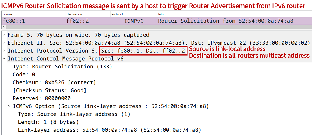
FF02::1 - this is the All Nodes multicast address to reach all devices on a local network segment. For example, the Neighbor Discovery Protocol (NDP) uses this address in the Router Advertisement (RA) messages with Stateless Address Autoconfiguration (SLAAC).
FF02::2 - this is the All Routers multicast address used by IPv6-capable routers to receive NDP Router Solicitation (RS) messages.
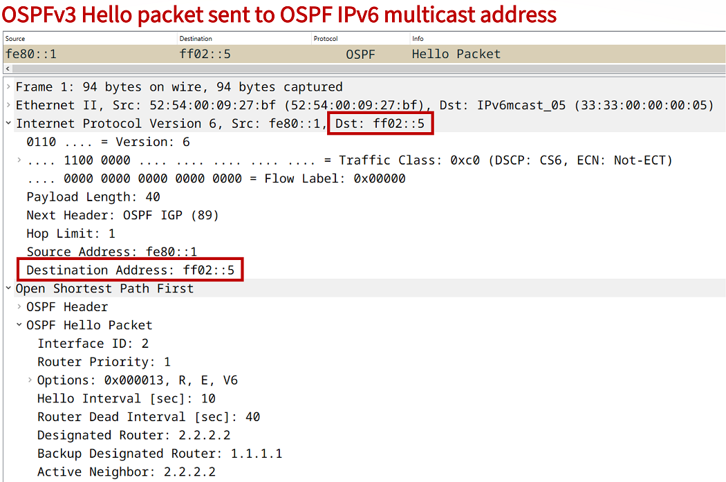
FF02::5 - this is the OSPFv3 multicast address used by the OSPF Hello packet.
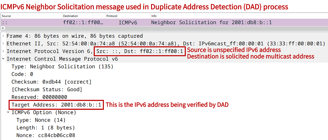
Note that IPv6 also has a Solicited Node multicast address which is used by NDP in order to resolve the Layer-2 MAC address of a device (similar to ARP in IPv4). It is also used for the purpose of Duplicate Address Detection (DAD) by sending an NDP Neighbor Solicitation message to the Solicited Node Multicast Group (SNMG) address.
Regarding configuration of IPv6 multicast routing, the PIM Sparse Mode Rendezvous Point (RP) address can either be configured statically or with Bootstrap Router (BSR). Auto-RP is not supported in IPv6 multicast. However, in IPv6 there is also an option to configure an embedded RP address. With IPv6 embedded RP the address of the Rendezvous Point is encoded in the multicast group address, which has the reserved prefix FF70::/12. Embedded RP is detailed in RFC 3956
What is multicast vs broadcast?
Multicast and Broadcast comparison
Multicast
Broadcast
Sent to a group of receivers.
Sent to all devices on a network segment.
Only devices that are interested in a multicast stream receive the data. Receivers can join and leave a multicast group dynamically.
All devices unconditionally receive broadcast traffic, and a device that it is not interested in the broadcast needs to drop those packets.
A multicast source can send a stream to a group address by routing IP multicast traffic across different network segments (with the help of PIM). As a result, receivers in different network segments can join a common multicast group address.
Broadcast traffic is limited within a local network segment. All devices on a local subnetwork receive the broadcast, and devices on different networks cannot receive traffic sent to a broadcast address.
Mapping multicast IP to MAC address
The Layer-2 Ethernet standard supports multicast destination MAC addresses so that IP multicast can function. A Layer-2 switch that receives a frame with a multicast destination MAC address sends it out all ports except on the one it was received. This flooding behavior can be controlled with IGMP Snooping. In summary, it is important that there exists a standard Ethernet frame destination address to distinguish multicast from unicast and broadcast traffic types.
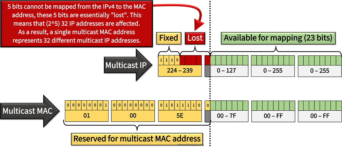
The mechanism to map a multicast IP address to a MAC address must comply with the defined address formats. Namely, within a 48-bit multicast MAC address there are only 23-bits available to insert an IPv4 address. As a result, each individual multicast MAC address actually represents 32 different multicast IPv4 addresses. The following image provides further details.
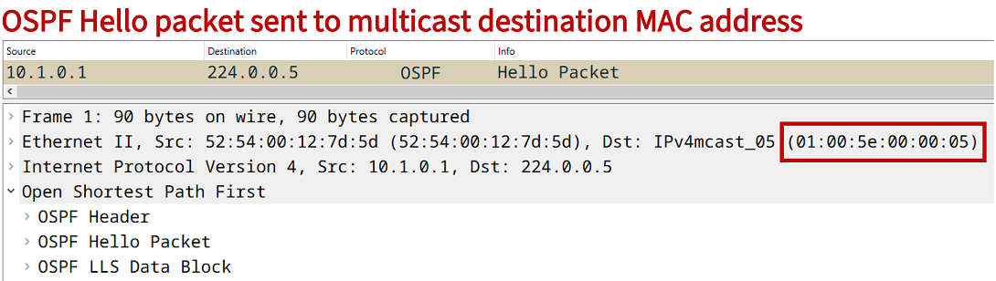
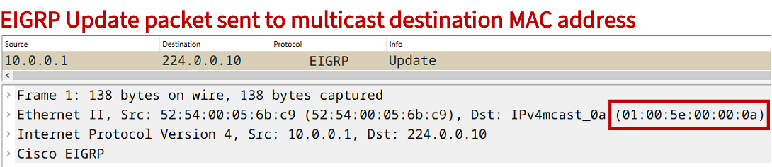
This also has implications on IP multicast addressing schemes. For example, the multicast group IP addresses 224.128.0.5, 224.0.0.5 and 239.0.0.5 map to the single MAC address 01:00:5e:00:00:05. Or the addresses 224.128.0.10, 224.0.0.10 and 239.0.0.10 map to the MAC address 01:00:5e:00:00:0a. Notice that these MAC addresses are also used by OSPF and EIGRP respectively.
Thus, in a production network it is important to select multicast group addresses in a way that a multicast stream does not interfere with an existing protocol's control plane functions. In this blog post for simplicity the administratively scoped (Organization-Local Scope) IPv4 multicast group address 239.0.0.1 and 239.0.0.2 are used.
What is a Multicast Distribution Tree (MDT)?
In order to connect multicast sources with interested receivers Protocol Independent Multicast (PIM) calculates a tree structure. There are two types of MDT architectures in use.
A Source-Based Tree which is also called a Shortest Path Tree (SPT) has the First Hop Router (FHR) at its root. For example, PIM Dense Mode and PIM Source-Specific Multicast (PIM SSM) only create Source-Based Trees. The notation of such a tree is (S,G) where the "S" stands for the unicast address of the multicast source and "G" stands for the multicast group address. PIM Sparse Mode uses an (S,G) tree between the Rendezvous Point (RP) and the FHR, and can also build an (S,G) tree after SPT switchover has taken place.
A Shared Distribution Tree is also called a Rendezvous Point Tree (RPT) and has the RP at its root. For example, PIM Sparse Mode and Bidirection PIM use Shared Trees. The notation of such a tree is (*,G) where the star (*) implies that the source of the multicast stream is unknown. Specifically, it is the role of the RP to connect the multicast source with the interested receivers.
Additionally, service provider multicast VPNs (mVPN) also implement an MDT in their core infrastructure. When used with mVPN, the MDT is called a PMSI (Provider Multicast Service Interface), the term is described in RFC 6513. Two types of MDT are used with mVPN.
A Default MDT is more scalable than a Partitioned MDT and it is less complex to implement. With Default MDT a multicast stream is flooded to each PE router in the service provider core. PE routers that do not have connected receivers will drop the flooded multicast stream. A Default MDT's network resource utilization is less optimal when compared to a Partitioned MDT.
A Partitioned MDT is an on-demand core tree where a multicast stream is only sent to PEs that have connected receivers.
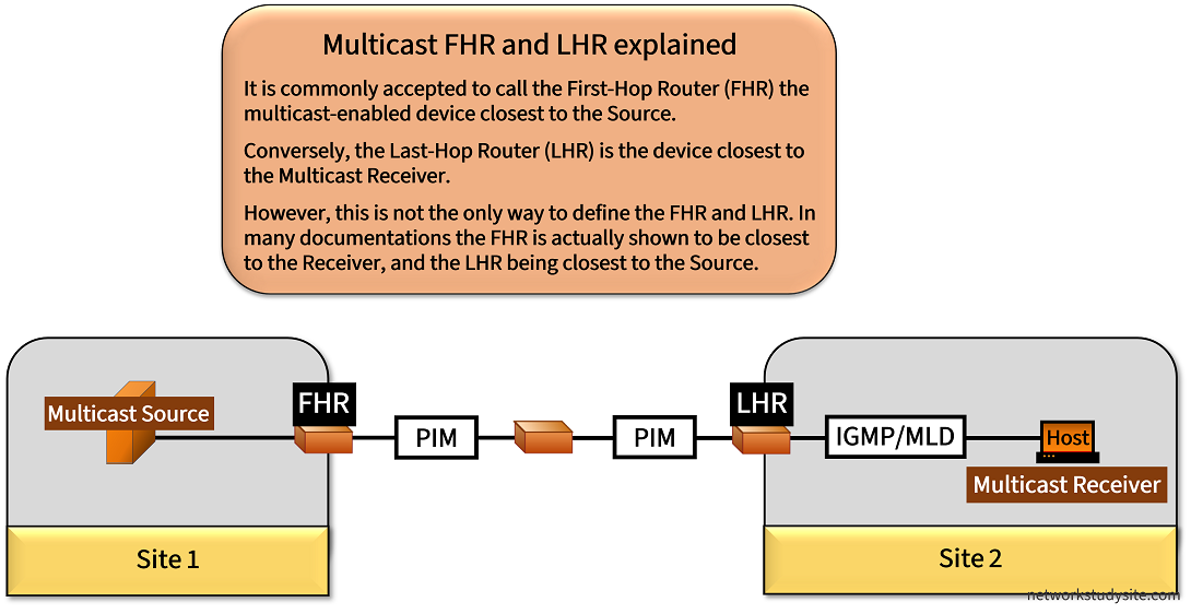
Multicast First-Hop Router and Last-Hop Router explained
The First-Hop Router (FHR) and Last-Hop Router (LHR) are central to understanding multicast concepts, however there are different approaches to defining them. One common approach is to call the FHR the multicast network device which is closest to the source, and the LHR is closest to the multicast receivers (the end hosts). This definition is also used throughout the current blog post.
The following table highlights several functions of the FHR and LHR based on the above definition.
Multicast FHR and LHR functions
FHR (closest to source)
LHR (closest to receiver)
Sends PIM Register message to Rendezvous Point (RP) in PIM Sparse Mode.
Sends Join message to RP in PIM Sparse Mode, and sends Prune message in PIM Dense Mode. Also, the LHR initiates the Graft message in PIM Dense Mode to rejoin a pruned tree.
Is the root of the Source-Based Tree (S,G).
Initiates PIM Join message to create Source Tree (S,G) during SPT switchover in PIM Sparse Mode.
Receives multicast data stream sent to the Group Address directly from the source. In PIM Sparse Mode FHR sends encapsulated PIM Register message to the RP, and in PIM Dense Mode FHR floods the multicast stream to all PIM-enabled routers in the domain.
Receives IGMP (IPv4) or MLD (IPv6) messages from the end hosts (receivers) that request a particular multicast stream. LHR translates IGMP/MLD Join messages into PIM Join/Prune messages.
As mentioned however, the definitions of the FHR and LHR may differ depending on the documentation used and the point of view. For example, the RFC 5110 mentions the FHR being the router closest to the receiver when describing the process from the end host's (receiver) point of view. The relevant quote is shown below.
When a host wants to receive a transmission, it first needs to find out the multicast group address (and with SSM, source address) using various means (e.g., SDP description file [RFC4566] or manually). Then it will signal its interest to its first-hop router using IGMP (IPv4) or MLD (IPv6) (Section 2.6).
RFC 5110, Overview of the Internet Multicast Routing Architecture
Configuring PIM Dense Mode and introduction to multicast basic concepts
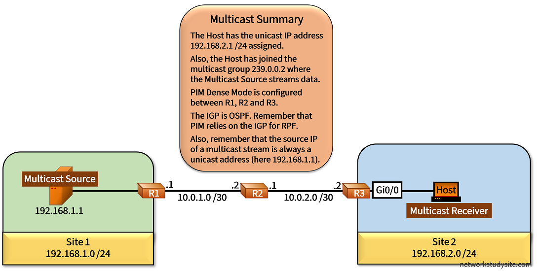
In the following example scenario, PIM Dense Mode (DM) floods the multicast stream from R1 (First Hop Router) through R3 (Last Hop Router) to the receiver listening to group address 239.0.0.2.
To enable multicast routing, each router has the command ip multicast-routing added in global configuration mode. Most importantly, there needs to be unicast network connectivity between Site 1 and Site 2 for PIM to work. This is accomplished by configuring OSPF between R1, R2 and R3. Finally, to enable PIM DM each router interface receives the command ip pim dense-mode.
The Host is configured with the interface level command ip igmp join-group 239.0.0.2 which signals its intent on the local LAN segment to join the multicast group address 239.0.0.2. R3 receives the IGMP join message and adds its interface Gi0/0 to the OIL for the group address 239.0.0.2. On R3, the Source Based Tree (S,G) entry is created because PIM DM floods the traffic throughout the multicast-enabled path while the Host requests the stream with IGMP. The following output from R3 displays this entry.
R3#show ip mroute 239.0.0.2 | beg Inter« Before IGMP join is received on R3 from the Host
Interface state: Interface, Next-Hop or VCD, State/Mode
(*, 239.0.0.2), 02:42:46/00:01:10, RP 0.0.0.0, flags: D
Incoming interface: Null, RPF nbr 0.0.0.0
Outgoing interface list:
GigabitEthernet0/1, Forward/Dense, 02:42:46/stopped
R3#show ip mroute 239.0.0.2 | beg Inter« After IGMP join is received on R3 from the Host
Interface state: Interface, Next-Hop or VCD, State/Mode
(*, 239.0.0.2), 02:43:45/stopped, RP 0.0.0.0, flags: DC
Incoming interface: Null, RPF nbr 0.0.0.0
Outgoing interface list:
GigabitEthernet0/0, Forward/Dense, 00:00:44/stopped
GigabitEthernet0/1, Forward/Dense, 02:43:45/stopped
(192.168.1.1, 239.0.0.2), 00:00:08/00:02:51, flags: T « (S,G) entry
Incoming interface: GigabitEthernet0/1, RPF nbr 10.0.2.1
Outgoing interface list: « This is the OILGigabitEthernet0/0, Forward/Dense, 00:00:08/stopped « Outgoing interface towards the Host is added to OIL
Configuration:
R1
R1#show run | sec ^ip multi
ip multicast-routing

R1#show run int Gi0/0 | sec int
interface GigabitEthernet0/0
 description ** to Source **
 ip address 192.168.1.2 255.255.255.0
 ip pim sparse-mode
 duplex auto
 speed auto
 media-type rj45

R1#show run int Gi0/1 | sec int
interface GigabitEthernet0/1
 description ** to R2 **
 ip address 10.0.1.1 255.255.255.252
 ip pim dense-mode
 ip ospf network point-to-point
 duplex auto
 speed auto
 media-type rj45

R1#show run | sec ^router
router ospf 10
 router-id 1.1.1.1
 passive-interface GigabitEthernet0/0
 network 10.0.1.0 0.0.0.3 area 0
 network 192.168.1.0 0.0.0.255 area 0
R2
R2#show run | sec ^ip multi
ip multicast-routing

R2#show run int Gi0/0 | sec int
interface GigabitEthernet0/0
 description ** to R1 **
 ip address 10.0.1.2 255.255.255.252
 ip pim dense-mode
 ip ospf network point-to-point
 duplex auto
 speed auto

R2#show run int Gi0/1 | sec int
interface GigabitEthernet0/1
 description ** to R3 **
 ip address 10.0.2.1 255.255.255.252
 ip pim dense-mode
 ip ospf network point-to-point
 duplex auto
 speed auto

R2#show run | sec ^router
router ospf 10
 router-id 2.2.2.2
 network 10.0.1.0 0.0.0.3 area 0
 network 10.0.2.0 0.0.0.3 area 0
R3
R3#show run | sec ^ip multi
ip multicast-routing

R3#show run int Gi0/0 | sec int
interface GigabitEthernet0/0
 description ** to Receiver **
 ip address 192.168.2.2 255.255.255.0
 ip pim dense-mode
 duplex auto
 speed auto
 media-type rj45

R3#show run int Gi0/1 | sec int
interface GigabitEthernet0/1
 description ** to R2 **
 ip address 10.0.2.2 255.255.255.252
 ip pim dense-mode
 ip ospf network point-to-point
 duplex auto
 speed auto
 media-type rj45

R3#show run | sec ^router
router ospf 10
 router-id 3.3.3.3
 passive-interface GigabitEthernet0/0
 network 10.0.2.0 0.0.0.3 area 0
 network 192.168.2.0 0.0.0.255 area 0
Multicast Source
Source#show run int Gi0/0 | sec int
interface GigabitEthernet0/0
 description ** to R1 **
 ip address 192.168.1.1 255.255.255.0
 duplex auto
 speed auto
 media-type rj45

Source#show run | sec ^ip route
ip route 0.0.0.0 0.0.0.0 GigabitEthernet0/0 192.168.1.2
Multicast Receiver
Receiver#show run int Gi0/0 | sec int
interface GigabitEthernet0/0
 description ** to R2 **
 ip address 192.168.2.1 255.255.255.0
 ip igmp join-group 239.0.0.2
 duplex auto
 speed auto
 media-type rj45

Receiver#show run | sec ^ip route
ip route 0.0.0.0 0.0.0.0 GigabitEthernet0/0 192.168.2.2
Receiver#show ip igmp group
IGMP Connected Group Membership
Group Address Interface Uptime Expires Last Reporter Group Accounted
239.0.0.2 GigabitEthernet0/0 00:54:04 never 192.168.2.1 « The Host has joined this multicast groupSource#ping 239.0.0.2 re 5
Type escape sequence to abort.
Sending 5, 100-byte ICMP Echos to 239.0.0.2, timeout is 2 seconds:
Reply to request 0 from 192.168.2.1, 3 ms « The Source gets a reply from the Host on the multicast group
Reply to request 1 from 192.168.2.1, 3 ms
Reply to request 2 from 192.168.2.1, 3 ms
Reply to request 3 from 192.168.2.1, 4 ms
Reply to request 4 from 192.168.2.1, 3 ms
R1#mtrace 10.0.2.2 10.0.1.1
Type escape sequence to abort.
Mtrace from 10.0.2.2 to 10.0.1.1 via RPF« mtrace shows Reverse Path Forwarding route calculated by IGP OSPF
From source (?) to destination (?)
Querying full reverse path...
0 10.0.1.1
-1 10.0.1.1 ==> 10.0.1.1 PIM [10.0.2.0/30]
-2 10.0.1.2 ==> 10.0.2.1 PIM_MT [10.0.2.0/30]
-3 10.0.2.2
R1#mtrace 10.0.1.1 10.0.2.2
Type escape sequence to abort.
Mtrace from 10.0.1.1 to 10.0.2.2 via RPF
From source (?) to destination (?)
Querying full reverse path...
0 10.0.2.2
-1 10.0.2.2 ==> 10.0.2.2 PIM [10.0.1.0/30]
-2 10.0.2.1 ==> 10.0.1.2 PIM_MT [10.0.1.0/30]
-3 10.0.1.1
R1#mtrace 10.0.2.2 10.0.1.1 239.0.0.2
Type escape sequence to abort.
Mtrace from 10.0.2.2 to 10.0.1.1 via group 239.0.0.2« mtrace can be used to analyze the path for different multicast groups
From source (?) to destination (?)
Querying full reverse path...
0 10.0.1.1
-1 10.0.1.1 ==> 10.0.1.1 PIM [10.0.2.0/30]
-2 10.0.1.2 ==> 10.0.2.1 PIM_MT [10.0.2.0/30]
-3 10.0.2.2
Configuring PIM SSM and understanding multicast routing table (static mroute)
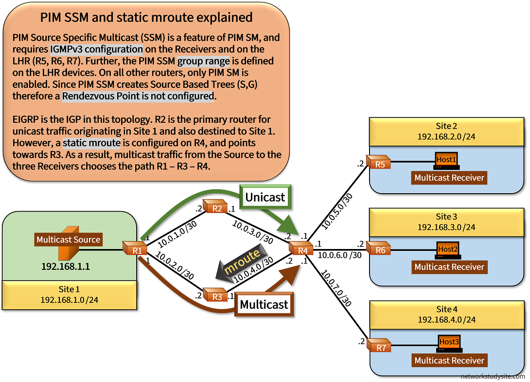
In the following example topology, PIM Source Specific Multicast is configured on the routers and this means there is no Rendezvous Point (RP) needed. However, the Last-Hop Routers (LHR) R5, R6 and R7 need to support PIM SSM and also IGMPv3. Moreover, IGMPv3 also needs to be supported on the Multicast Receivers (the hosts).
In PIM SSM the Receivers must already know the unicast IP address of the multicast Source. So the Receivers send IGMPv3 Membership Reports with the Multicast Group address (in the current example 239.0.0.1) and with a corresponding Multicast Source address 192.168.1.1 (located in Site 1). Using this information, the PIM-enabled Last Hop Routers build a Source Based (S,G) Tree rooted at the FHR R1. As a result, the Receivers only accept a multicast stream to 239.0.0.1 from the single source address 192.168.1.1.
Additionally in this scenario, multicast routing diverges from the path calculated by EIGRP. An Offset List configured on R3 ensures that EIGRP chooses R2 as the preferred primary next-hop router for unicast traffic leaving (egress) Site 1. However, a static mroute is configured on R4 pointing towards R3. This is achieved with the global configuration command ip mroute 192.168.1.0 255.255.255.0 10.0.4.1 issued on R4. And as a result, the multicast stream from Site 1 chooses R3 as its preferred path, while the unicast traffic chooses R2.
Configuration:
R1
R1#show run | sec ^ip multi
ip multicast-routing

R1#show run int Gi0/0 | sec int
interface GigabitEthernet0/0
 description ** to Source **
 ip address 192.168.1.2 255.255.255.0
 ip pim sparse-mode
 duplex auto
 speed auto
 media-type rj45

R1#show run int Gi0/1 | sec int
interface GigabitEthernet0/1
 description ** to R2 **
 ip address 10.0.1.1 255.255.255.252
 ip pim sparse-mode
 duplex auto
 speed auto
 media-type rj45

R1#show run | sec ^router
router eigrp EXAMPLE-EIGRP
 !
 address-family ipv4 unicast autonomous-system 10
  !
  af-interface GigabitEthernet0/0
   passive-interface
  exit-af-interface
  !
  topology base
  exit-af-topology
  network 10.0.1.0 0.0.0.3
  network 10.0.2.0 0.0.0.3
  network 192.168.1.0
  eigrp router-id 1.1.1.1
 exit-address-family
R2
R2#show run | sec ^ip multi
ip multicast-routing

R2#show run int Gi0/0 | sec int
interface GigabitEthernet0/0
 description ** to R1 **
 ip address 10.0.1.2 255.255.255.252
 ip pim sparse-mode
 duplex auto
 speed auto
 media-type rj45

R2#show run int Gi0/1 | sec int
interface GigabitEthernet0/1
 description ** to R4 **
 ip address 10.0.3.1 255.255.255.252
 ip pim sparse-mode
 duplex auto
 speed auto
 media-type rj45

R2#show run | sec ^router
router eigrp EXAMPLE-EIGRP
 !
 address-family ipv4 unicast autonomous-system 10
  !
  topology base
  exit-af-topology
  network 10.0.1.0 0.0.0.3
  network 10.0.3.0 0.0.0.3
  eigrp router-id 2.2.2.2
 exit-address-family
R3
R3#show run | sec ^ip multi
ip multicast-routing

R3#show run int Gi0/0 | sec int
interface GigabitEthernet0/0
 description ** to R1 **
 ip address 10.0.2.2 255.255.255.252
 ip pim sparse-mode
 duplex auto
 speed auto
 media-type rj45

R3#show run int Gi0/1 | sec int
interface GigabitEthernet0/1
 description ** to R4 **
 ip address 10.0.4.1 255.255.255.252
 ip pim sparse-mode
 duplex auto
 speed auto
 media-type rj45

R3#show run | sec ^router
router eigrp EXAMPLE-EIGRP
 !
 address-family ipv4 unicast autonomous-system 10
  !
  topology base
   offset-list ACL-OFFSET-LIST out 1000 GigabitEthernet0/1
   offset-list ACL-OFFSET-LIST out 1000 GigabitEthernet0/0
  exit-af-topology
  network 10.0.2.0 0.0.0.3
  network 10.0.4.0 0.0.0.3
  eigrp router-id 3.3.3.3
 exit-address-family

R3#show run | sec ^ip access
ip access-list standard ACL-OFFSET-LIST
 permit 192.168.1.0 0.0.0.255
 permit 192.168.2.0 0.0.0.255
 permit 192.168.3.0 0.0.0.255
 permit 192.168.4.0 0.0.0.255
R4
R4#show run | sec ^ip multi
ip multicast-routing

R4#show run | sec ^ip mroute
ip mroute 192.168.1.0 255.255.255.0 10.0.4.1

R4#show run int Gi0/0 | sec int
interface GigabitEthernet0/0
 description ** to R2 **
 ip address 10.0.3.2 255.255.255.252
 ip pim sparse-mode
 duplex auto
 speed auto
 media-type rj45

R4#show run int Gi0/1 | sec int
interface GigabitEthernet0/1
 description ** to R3 **
 ip address 10.0.4.2 255.255.255.252
 ip pim sparse-mode
 duplex auto
 speed auto
 media-type rj45

R4#show run int Gi0/2 | sec int
interface GigabitEthernet0/2
 description ** to R5 **
 ip address 10.0.5.1 255.255.255.252
 ip pim sparse-mode
 duplex auto
 speed auto
 media-type rj45

R4#show run int Gi0/3 | sec int
interface GigabitEthernet0/3
 description ** to R6 **
 ip address 10.0.6.1 255.255.255.252
 ip pim sparse-mode
 duplex auto
 speed auto
 media-type rj45

R4#show run int Gi0/4 | sec int
interface GigabitEthernet0/4
 description ** to R7 **
 ip address 10.0.7.1 255.255.255.252
 ip pim sparse-mode
 duplex auto
 speed auto
 media-type rj45

R4#show run | sec ^router
router eigrp EXAMPLE-EIGRP
 !
 address-family ipv4 unicast autonomous-system 10
  !
  topology base
  exit-af-topology
  network 10.0.3.0 0.0.0.3
  network 10.0.4.0 0.0.0.3
  network 10.0.5.0 0.0.0.3
  network 10.0.6.0 0.0.0.3
  network 10.0.7.0 0.0.0.3
  eigrp router-id 4.4.4.4
 exit-address-family
R5
R5#show run | sec ^ip multi
ip multicast-routing

R5#show run | sec ^ip pim
ip pim ssm range ACL-PIM-SSM

R5#show run | sec ^ip access
ip access-list standard ACL-PIM-SSM
 permit 239.0.0.1

R5#show run int Gi0/0 | sec int
interface GigabitEthernet0/0
 description ** to R4 **
 ip address 10.0.5.2 255.255.255.252
 ip pim sparse-mode
 duplex auto
 speed auto
 media-type rj45

R5#show run int Gi0/1 | sec int
interface GigabitEthernet0/1
 description ** to Host1 **
 ip address 192.168.2.2 255.255.255.0
 ip pim sparse-mode
 ip igmp version 3
 duplex auto
 speed auto
 media-type rj45

R5#show run | sec ^router
router eigrp EXAMPLE-EIGRP
 !
 address-family ipv4 unicast autonomous-system 10
  !
  af-interface GigabitEthernet0/1
   passive-interface
  exit-af-interface
  !
  topology base
  exit-af-topology
  network 10.0.5.0 0.0.0.3
  network 192.168.2.0
  eigrp router-id 5.5.5.5
 exit-address-family
R6
R6#show run | sec ^ip multi
ip multicast-routing

R6#show run | sec ^ip pim
ip pim ssm range ACL-PIM-SSM

R6#show run | sec ^ip access
ip access-list standard ACL-PIM-SSM
 permit 239.0.0.1

R6#show run int Gi0/0 | sec int
interface GigabitEthernet0/0
 description ** to R4 **
 ip address 10.0.6.2 255.255.255.252
 ip pim sparse-mode
 duplex auto
 speed auto
 media-type rj45

R6#show run int Gi0/1 | sec int
interface GigabitEthernet0/1
 description ** to Host2 **
 ip address 192.168.3.2 255.255.255.0
 ip pim sparse-mode
 ip igmp version 3
 duplex auto
 speed auto
 media-type rj45

R6#show run | sec ^router
router eigrp EXAMPLE-EIGRP
 !
 address-family ipv4 unicast autonomous-system 10
  !
  af-interface GigabitEthernet0/1
   passive-interface
  exit-af-interface
  !
  topology base
  exit-af-topology
  network 10.0.6.0 0.0.0.3
  network 192.168.3.0
  eigrp router-id 6.6.6.6
 exit-address-family
R7
R7#show run | sec ^ip multi
ip multicast-routing

R7#show run | sec ^ip pim
ip pim ssm range ACL-PIM-SSM

R7#show run | sec ^ip access
ip access-list standard ACL-PIM-SSM
 permit 239.0.0.1

R7#show run int Gi0/0 | sec int
interface GigabitEthernet0/0
 description ** to R4 **
 ip address 10.0.7.2 255.255.255.252
 ip pim sparse-mode
 duplex auto
 speed auto
 media-type rj45

R7#show run int Gi0/1 | sec int
interface GigabitEthernet0/1
 description ** to Host3 **
 ip address 192.168.4.2 255.255.255.0
 ip pim sparse-mode
 ip igmp version 3
 duplex auto
 speed auto
 media-type rj45

R7#show run | sec ^router
router eigrp EXAMPLE-EIGRP
 !
 address-family ipv4 unicast autonomous-system 10
  !
  af-interface GigabitEthernet0/1
   passive-interface
  exit-af-interface
  !
  topology base
  exit-af-topology
  network 10.0.7.0 0.0.0.3
  network 192.168.4.0
  eigrp router-id 7.7.7.7
 exit-address-family
Multicast Source
Source#show run int Gi0/0 | sec int
interface GigabitEthernet0/0
 description ** to R1 **
 ip address 192.168.1.1 255.255.255.0
 duplex auto
 speed auto
 media-type rj45

Source#show run | sec ^ip route
ip route 0.0.0.0 0.0.0.0 GigabitEthernet0/0 192.168.1.2
Host1
Host1#show run int Gi0/0 | sec int
interface GigabitEthernet0/0
 description ** to R5 **
 ip address 192.168.2.1 255.255.255.0
 ip igmp join-group 239.0.0.1 source 192.168.1.1
 ip igmp version 3
 duplex auto
 speed auto
 media-type rj45

Host1#show run | sec ^ip route
ip route 0.0.0.0 0.0.0.0 GigabitEthernet0/0 192.168.2.2
Host2
Host2#show run int Gi0/0 | sec int
interface GigabitEthernet0/0
 description ** to R6 **
 ip address 192.168.3.1 255.255.255.0
 ip igmp join-group 239.0.0.1 source 192.168.1.1
 ip igmp version 3
 duplex auto
 speed auto
 media-type rj45

Host2#show run | sec ^ip route
ip route 0.0.0.0 0.0.0.0 GigabitEthernet0/0 192.168.3.2
Source#ping 239.0.0.1 re 2
Type escape sequence to abort.
Sending 2, 100-byte ICMP Echos to 239.0.0.1, timeout is 2 seconds: « Hosts receive the multicast stream
Reply to request 0 from 192.168.3.1, 6 ms
Reply to request 0 from 192.168.2.1, 7 ms
Reply to request 0 from 192.168.4.1, 6 ms
Reply to request 1 from 192.168.2.1, 5 ms
Reply to request 1 from 192.168.4.1, 5 ms
Reply to request 1 from 192.168.3.1, 5 ms
R5#show ip mroute
IP Multicast Routing Table
Flags: D - Dense, S - Sparse, B - Bidir Group, s - SSM Group, C - Connected,
L - Local, P - Pruned, R - RP-bit set, F - Register flag,
T - SPT-bit set, J - Join SPT, M - MSDP created entry, E - Extranet,
X - Proxy Join Timer Running, A - Candidate for MSDP Advertisement,
U - URD, I - Received Source Specific Host Report,
Z - Multicast Tunnel, z - MDT-data group sender,
Y - Joined MDT-data group, y - Sending to MDT-data group,
G - Received BGP C-Mroute, g - Sent BGP C-Mroute,
N - Received BGP Shared-Tree Prune, n - BGP C-Mroute suppressed,
Q - Received BGP S-A Route, q - Sent BGP S-A Route,
V - RD & Vector, v - Vector, p - PIM Joins on route,
x - VxLAN group
Outgoing interface flags: H - Hardware switched, A - Assert winner, p - PIM Join
Timers: Uptime/Expires
Interface state: Interface, Next-Hop or VCD, State/Mode
(192.168.1.1, 239.0.0.1), 02:35:15/00:02:42, flags: sTI« (S,G) state entry with flags for PIM SSM
Incoming interface: GigabitEthernet0/0, RPF nbr 10.0.5.1
Outgoing interface list:
GigabitEthernet0/1, Forward/Sparse, 02:35:15/00:02:42
(*, 224.0.1.40), 02:56:30/00:01:54, RP 0.0.0.0, flags: DCL
Incoming interface: Null, RPF nbr 0.0.0.0
Outgoing interface list:
GigabitEthernet0/0, Forward/Sparse, 02:56:29/00:01:54
R1#trace 192.168.2.1 source 192.168.1.2 probe 1
Type escape sequence to abort.
Tracing the route to 192.168.2.1
VRF info: (vrf in name/id, vrf out name/id)
1 10.0.1.2 2 msec « Unicast traffic transmitted through R2
2 10.0.3.2 2 msec
3 10.0.5.2 4 msec
4 192.168.2.1 4 msec
R1#mtrace 192.168.1.2 192.168.2.2
Type escape sequence to abort.
Mtrace from 192.168.1.2 to 192.168.2.2 via RPF
From source (?) to destination (?)
Querying full reverse path...
0 192.168.2.2
-1 10.0.5.2 ==> 10.0.5.2 PIM [192.168.1.0/24]
-2 10.0.5.1 ==> 10.0.4.2 PIM_MT [192.168.1.0/24]
-3 10.0.4.1 ==> 10.0.2.2 PIM [192.168.1.0/24] « Multicats traffic transmitted through R3
-4 10.0.2.1 ==> 192.168.1.2 PIM_MT [192.168.1.2/32]
-5 192.168.1.2
R4#show ip mroute | beg Int
Interface state: Interface, Next-Hop or VCD, State/Mode
(*, 239.0.0.1), 02:58:40/stopped, RP 0.0.0.0, flags: SP
Incoming interface: Null, RPF nbr 0.0.0.0
Outgoing interface list: Null
(192.168.1.1, 239.0.0.1), 00:07:40/00:01:43, flags: T
Incoming interface: GigabitEthernet0/1, RPF nbr 10.0.4.1, Mroute« Static mroute configured towards R3
Outgoing interface list:
GigabitEthernet0/3, Forward/Sparse, 00:07:09/00:03:13 « OIL contains outgoing interfaces used to reach ReceiversGigabitEthernet0/2, Forward/Sparse, 00:07:13/00:03:08
GigabitEthernet0/4, Forward/Sparse, 00:07:40/00:02:41
(*, 224.0.1.40), 03:03:38/00:02:53, RP 0.0.0.0, flags: DCL
Incoming interface: Null, RPF nbr 0.0.0.0
Outgoing interface list:
GigabitEthernet0/0, Forward/Sparse, 03:03:37/00:02:53
R4#show ip mroute static
Mroute: 192.168.1.0/24, RPF neighbor: 10.0.4.1, distance: 1 « Static mroute configured to R3R4#show ip pim interface count
For switching state use "show ip mfib interface"
Address Interface Mpackets In/Out
10.0.3.2 GigabitEthernet0/0 3/3
10.0.4.2 GigabitEthernet0/1 401/0 « On R4 multicast traffic incoming from R3
10.0.5.1 GigabitEthernet0/2 0/152
10.0.6.1 GigabitEthernet0/3 0/321
10.0.7.1 GigabitEthernet0/4 0/399
Note that in this example the Group Address 239.0.0.1 is used, however in a production network it is more likely that the reserved PIM SSM Group Address range 232.0.0.0 /8 will be configured. The following output shows the options available when configuring the PIM SSM range.
Router(config)#ip pim ssm ?default Use 232/8 group range for SSM
range ACL for group range to be used for SSM
The PIM SSM address range is defined for the IPv4 and also for the IPv6 address-family. The corresponding RFC 4607 provides further details which are quoted below.
IP version 4 (IPv4) addresses in the 232/8 (232.0.0.0 to 232.255.255.255) range are designated as source-specific multicast (SSM) destination addresses and are reserved for use by source-specific applications and protocols. For IP version 6 (IPv6), the address prefix FF3x::/32 is reserved for source-specific multicast use.
RFC 4607, Source-Specific Multicast for IP
What is the difference between joining a multicast group vs joining a multicast tree?
Receivers of multicast traffic must first join a multicast group. This is accomplished with the IGMP protocol. The following packet capture shows a Membership Report (join message) sent to the multicast address 224.0.0.22 which is used by IGMPv3-capable devices. The message requests to join the group address 239.1.1.1 in order to receive a multicast stream from the source IP 192.168.1.1.
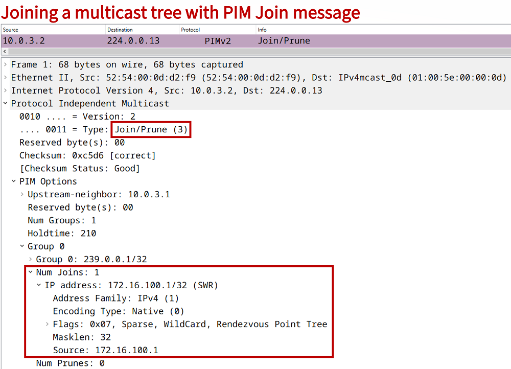
In contrast, routers can join a multicast tree in order to forward traffic to a multicast group. A router can use PIM to join a multicast tree. The following capture displays a PIM Sparse Mode join message sent from a Last Hop Router and destined to a Rendezvous Point (RP) to establish a Shared (*,G) Tree. Remember, in PIM Sparse Mode the root of the (*,G) tree is the RP.
Configuring PIM Sparse Mode across site-to-site GRE/IPSec tunnel in VRF with EIGRP
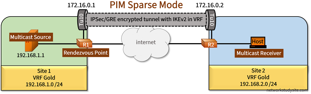
In the following example scenario, Site 1 and Site 2 are connected through an IPSec/GRE tunnel and use EIGRP to share unicast routes. PIM Sparse Mode (SM) is configured so the Host can receive the multicast stream on 239.0.0.1 from the Source in Site 1. PIM SM relies on a Rendezvous Point (RP) which is statically configured as R1 in this topology. Note that R1 is also the multicast First Hop Router (FHR).
Thus, as soon as R2 receives the IGMP Membership Report (join) message from the Host, R2 sends a PIM join message to the RP for the group 239.0.0.1, in order to create the Shared Distribution Tree (*,G). Thereafter, the RP can forward traffic from the Source to the Receiver in Site 2 over the encrypted IPSec tunnel.
Note that the two sites use VRF Gold to communicate, and this also needs to be reflected in the PIM configuration. For example, when enabling multicast routing the command ip multicast-routing vrf Gold is issued in global configuration mode.
Also, when configuring the RP address the command ip pim vrf Gold rp-address 1.1.1.1 is necessary. As visible, the Loopback IP address 1.1.1.1/32 on R1 is used as the RP address. It is important that this command be issued on the RP as well.
Configuration:
R1
R1#show run | sec ^ip multi
ip multicast-routing vrf Gold

R1#show run | sec ^ip pim
ip pim vrf Gold rp-address 1.1.1.1

R1#show run int Lo10 | sec int
interface Loopback10
 vrf forwarding Gold
 ip address 1.1.1.1 255.255.255.255

R1#show run int Gi0/0 | sec int
interface GigabitEthernet0/0
 description ** to Multicast Source **
 no ip address
 duplex auto
 speed auto
 media-type rj45

R1#show run int Gi0/0.1 | sec int
interface GigabitEthernet0/0.1
 description ** to Multicast Source in VRF Gold **
 encapsulation dot1Q 1 native
 vrf forwarding Gold
 ip address 192.168.1.2 255.255.255.0
 ip pim sparse-mode

R1#show run int Gi0/1 | sec int
interface GigabitEthernet0/1
 description ** to internet **
 ip address 10.10.0.1 255.255.255.252
 duplex auto
 speed auto
 media-type rj45

R1#show run int Tu10 | sec int
interface Tunnel10
 vrf forwarding Gold
 ip address 172.16.0.1 255.255.255.252
 ip pim sparse-mode
 tunnel source GigabitEthernet0/1
 tunnel destination 10.20.0.1
 tunnel protection ipsec profile CRYPTO-IPSEC-PROFILE

R1#show run | sec ^router
router eigrp EXAMPLE-EIGRP
 !
 address-family ipv4 unicast vrf Gold autonomous-system 10
  !
  topology base
  exit-af-topology
  network 1.1.1.1 0.0.0.0
  network 172.16.0.0 0.0.0.3
  network 192.168.1.0
 exit-address-family

R1#show run | sec ^crypto
crypto ikev2 proposal CRYPTO-PROPOSAL
 encryption aes-cbc-256
 integrity sha256
 group 1
crypto ikev2 policy CRYPTO-POLICY
 match address local 10.10.0.1
 proposal CRYPTO-PROPOSAL
crypto ikev2 keyring CRYPTO-KEYRING
 peer KEY-PEER
  address 10.20.0.1
  pre-shared-key p4ssw0rd.123
 !
crypto ikev2 profile CRYPTO-IKEV2-PROFILE
 match identity remote address 10.20.0.1 255.255.255.255
 authentication remote pre-share
 authentication local pre-share
 keyring local CRYPTO-KEYRING
crypto ipsec transform-set CRYPTO-TRANSFORM esp-aes
 mode transport
crypto ipsec profile CRYPTO-IPSEC-PROFILE
 set transform-set CRYPTO-TRANSFORM
 set ikev2-profile CRYPTO-IKEV2-PROFILE

R1#show run | sec ^ip route
ip route 0.0.0.0 0.0.0.0 GigabitEthernet0/1 10.10.0.2
R2
R2#show run | sec ^ip multi
ip multicast-routing vrf Gold

R2#show run | sec ^ip pim
ip pim vrf Gold rp-address 1.1.1.1

R2#show run int Gi0/0 | sec int
interface GigabitEthernet0/0
 description ** to Multicast Receiver **
 no ip address
 duplex auto
 speed auto
 media-type rj45

R2#show run int Gi0/0.1 | sec int
interface GigabitEthernet0/0.1
 description ** to Multicast Receiver in VRF Gold **
 encapsulation dot1Q 1 native
 vrf forwarding Gold
 ip address 192.168.2.2 255.255.255.0
 ip pim sparse-mode

R2#show run int Gi0/1 | sec int
interface GigabitEthernet0/1
 description ** to internet **
 ip address 10.20.0.1 255.255.255.252
 duplex auto
 speed auto
 media-type rj45

R2#show run int Tu10 | sec int
interface Tunnel10
 vrf forwarding Gold
 ip address 172.16.0.2 255.255.255.252
 ip pim sparse-mode
 tunnel source GigabitEthernet0/1
 tunnel destination 10.10.0.1
 tunnel protection ipsec profile CRYPTO-IPSEC-PROFILE

R2#show run | sec ^router
router eigrp EXAMPLE-EIGRP
 !
 address-family ipv4 unicast vrf Gold autonomous-system 10
  !
  topology base
  exit-af-topology
  network 172.16.0.0 0.0.0.3
  network 192.168.2.0
 exit-address-family

R2#show run | sec ^crypto
crypto ikev2 proposal CRYPTO-PROPOSAL
 encryption aes-cbc-256
 integrity sha256
 group 1
crypto ikev2 policy CRYPTO-POLICY
 match address local 10.20.0.1
 proposal CRYPTO-PROPOSAL
crypto ikev2 keyring CRYPTO-KEYRING
 peer KEY-PEER
  address 10.10.0.1
  pre-shared-key p4ssw0rd.123
 !
crypto ikev2 profile CRYPTO-IKEV2-PROFILE
 match identity remote address 10.10.0.1 255.255.255.255
 authentication remote pre-share
 authentication local pre-share
 keyring local CRYPTO-KEYRING
crypto ipsec transform-set CRYPTO-TRANSFORM esp-aes
 mode transport
crypto ipsec profile CRYPTO-IPSEC-PROFILE
 set transform-set CRYPTO-TRANSFORM
 set ikev2-profile CRYPTO-IKEV2-PROFILE

R2#show run | sec ^ip route
ip route 0.0.0.0 0.0.0.0 GigabitEthernet0/1 10.20.0.2
Multicast Source
Source#show run int Gi0/0 | sec int
interface GigabitEthernet0/0
 description ** to R1 **
 ip address 192.168.1.1 255.255.255.0
 duplex auto
 speed auto
 media-type rj45

Source#show run | sec ^ip route
ip route 0.0.0.0 0.0.0.0 GigabitEthernet0/0 192.168.1.2
Multicast Receiver
Host#show run int Gi0/0 | sec int
interface GigabitEthernet0/0
 description ** to R2 **
 ip address 192.168.2.1 255.255.255.0
 ip igmp join-group 239.0.0.1
 duplex auto
 speed auto
 media-type rj45

Host#show run | sec ^ip route
ip route 0.0.0.0 0.0.0.0 GigabitEthernet0/0 192.168.2.2
R1#show crypto session
Crypto session current status
Interface: Tunnel10
Profile: CRYPTO-IKEV2-PROFILE
Session status: UP-ACTIVE
Peer: 10.20.0.1 port 500
Session ID: 2
IKEv2 SA: local 10.10.0.1/500 remote 10.20.0.1/500 Active « IPSec tunnel created using IKEv2
IPSEC FLOW: permit 47 host 10.10.0.1 host 10.20.0.1
Active SAs: 2, origin: crypto map
R1#show crypto session brief
Status: A- Active, U - Up, D - Down, I - Idle, S - Standby, N - Negotiating
K - No IKE
ivrf = Gold
Peer I/F Username Group/Phase1_id Uptime Status
10.20.0.1 Tu10 10.20.0.1 00:07:52 UA« IPSec tunnel Up and ActiveR1#show eigrp address-family ipv4 vrf Gold neighbors
EIGRP-IPv4 VR(EXAMPLE-EIGRP) Address-Family Neighbors for AS(10)
VRF(Gold)
H Address Interface Hold Uptime SRTT RTO Q Seq
(sec) (ms) Cnt Num
0 172.16.0.2 Tu10 12 00:08:08 49 1470 0 3 « EIGRP neighborship in VRF Gold between R1 and R2R1#show ip route vrf Gold eigrp | beg Ga
Gateway of last resort is not set
D 192.168.2.0/24 [90/76805120] via 172.16.0.2, 00:08:22, Tunnel10« R1 learn Site 2 route through EIGRPSource#ping 239.0.0.1 re 2
Type escape sequence to abort.
Sending 2, 100-byte ICMP Echos to 239.0.0.1, timeout is 2 seconds: « Multicast stream received by the Host in Site 2
Reply to request 0 from 192.168.2.1, 90 ms
Reply to request 1 from 192.168.2.1, 47 ms
R1#show ip mroute vrf Gold
IP Multicast Routing Table
Flags: D - Dense, S - Sparse, B - Bidir Group, s - SSM Group, C - Connected,
L - Local, P - Pruned, R - RP-bit set, F - Register flag,
T - SPT-bit set, J - Join SPT, M - MSDP created entry, E - Extranet,
X - Proxy Join Timer Running, A - Candidate for MSDP Advertisement,
U - URD, I - Received Source Specific Host Report,
Z - Multicast Tunnel, z - MDT-data group sender,
Y - Joined MDT-data group, y - Sending to MDT-data group,
G - Received BGP C-Mroute, g - Sent BGP C-Mroute,
N - Received BGP Shared-Tree Prune, n - BGP C-Mroute suppressed,
Q - Received BGP S-A Route, q - Sent BGP S-A Route,
V - RD & Vector, v - Vector, p - PIM Joins on route,
x - VxLAN group
Outgoing interface flags: H - Hardware switched, A - Assert winner, p - PIM Join
Timers: Uptime/Expires
Interface state: Interface, Next-Hop or VCD, State/Mode
(*, 239.0.0.1), 00:23:16/stopped, RP 1.1.1.1, flags: SF« Shared Tree (*,G) state initiated by LHR R2
Incoming interface: Null, RPF nbr 0.0.0.0
Outgoing interface list:
Tunnel10, Forward/Sparse, 00:23:16/00:02:52
(192.168.1.1, 239.0.0.1), 00:00:11/00:02:48, flags: FT« Source Based Tree (S,G) state due to register process from Source
Incoming interface: GigabitEthernet0/0.1, RPF nbr 0.0.0.0
Outgoing interface list:
Tunnel10, Forward/Sparse, 00:00:11/00:03:18
(*, 224.0.1.40), 00:23:56/00:03:12, RP 1.1.1.1, flags: SJCL
Incoming interface: Null, RPF nbr 0.0.0.0
Outgoing interface list:
Tunnel10, Forward/Sparse, 00:23:23/00:03:12
GigabitEthernet0/0.1, Forward/Sparse, 00:23:55/00:02:09
R2#show ip mroute vrf Gold 239.0.0.1 | beg Int
Interface state: Interface, Next-Hop or VCD, State/Mode
(*, 239.0.0.1), 00:55:35/stopped, RP 1.1.1.1, flags: SJC « RP address is the source of the (*,G) tree
Incoming interface: Tunnel10, RPF nbr 172.16.0.1
Outgoing interface list:
GigabitEthernet0/0.1, Forward/Sparse, 00:55:35/00:02:51
(192.168.1.1, 239.0.0.1), 00:00:20/00:02:39, flags: JT
Incoming interface: Tunnel10, RPF nbr 172.16.0.1
Outgoing interface list:
GigabitEthernet0/0.1, Forward/Sparse, 00:00:20/00:02:51
R1#show ip pim vrf Gold rp mapping
PIM Group-to-RP Mappings
Group(s): 224.0.0.0/4, Static
RP: 1.1.1.1 (?)« R1 interface IP of Lo10 is statically configured as the RPR1#show ip pim vrf Gold TunnelTunnel0Type : PIM Encap« PIM SM Source Registration creates tunnels to encapsulate/decaps. PIM messages
RP : 1.1.1.1*
Source : 192.168.1.2
State : UP
Last event : Created (02:37:44)
Tunnel1*Type : PIM Decap
RP : 1.1.1.1*
Source : -
State : UP
Last event : Created (02:37:44)
The PIM packets and multicast stream are encrypted in the IPSec tunnel, however the following debug output from R1 (the RP) shows details of the mechanisms involved. The debug is specific to the group 239.0.0.1 in VRF Gold, therefore the debug ip pim vrf Gold 239.0.0.1 command is issued on R1.
R1#show log | beg Log Buffer
Log Buffer (8192 bytes):
PIM(1): Building Periodic (*,G) Join / (S,G,RP-bit) Prune message for 239.0.0.1
PIM(1): Received v2 Join/Prune on Tunnel10 from 172.16.0.2, to us« R2 sends (*,G) join to RP
PIM(1): Join-list: (*, 239.0.0.1), RPT-bit set, WC-bit set, S-bit set
PIM(1): Update Tunnel10/172.16.0.2 to (*, 239.0.0.1), Forward state, by PIM *G Join« Adding Tu10 to OIL
PIM(1): Adding register decap tunnel (Tunnel1) as accepting interface of (192.168.1.1, 239.0.0.1).
PIM(1): Adding register encap tunnel (Tunnel0) as forwarding interface of (192.168.1.1, 239.0.0.1).
PIM(1): Removing register decap tunnel (Tunnel1) as accepting interface of (192.168.1.1, 239.0.0.1).
PIM(1): Installing GigabitEthernet0/0.1 as accepting interface for (192.168.1.1, 239.0.0.1).
PIM(1): Received v2 Register on Loopback10 from 192.168.1.2 « PIM SM Source registration
for 192.168.1.1, group 239.0.0.1
PIM(1): Send v2 Register-Stop to 192.168.1.2 for 192.168.1.1, group 239.0.0.1
PIM(1): Received v2 Register-Stop on GigabitEthernet0/0.1 from 1.1.1.1
PIM(1): for source 192.168.1.1, group 239.0.0.1
PIM(1): Removing register encap tunnel (Tunnel0) as forwarding interface of (192.168.1.1, 239.0.0.1).
PIM(1): Clear Registering flag to 1.1.1.1 for (192.168.1.1/32, 239.0.0.1)
PIM(1): Received v2 Join/Prune on Tunnel10 from 172.16.0.2, to us
PIM(1): Join-list: (192.168.1.1/32, 239.0.0.1), S-bit set
PIM(1): Update Tunnel10/172.16.0.2 to (192.168.1.1, 239.0.0.1), Forward state, by PIM SG Join« SPT switchover
Notice in the above debug logs the PIM SM Registration process which is initiated by the First Hop Router (FHR) and destined to the RP in order to create a Source Based Tree (S,G). In this scenario, R1 is the FHR and also the RP.
Therefore, the PIM SM Registration happens on the same device, 192.168.1.2 is the LAN-facing interface (Gi0/0.1) on R1, and 1.1.1.1/32 (the RP address) is the Loopback interface on R1.
Configuring multicast BGP with PIM SSM and path control using BGP attributes
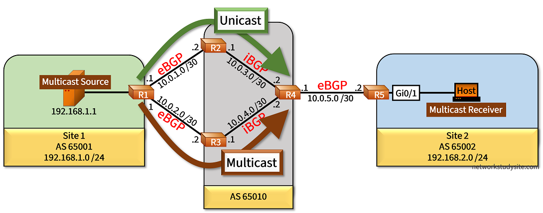
In the following example scenario, PIM Source-Specific Multicast (PIM SSM) is configured to carry the multicast stream from the Source in Site 1 to the Receiver in Site 2. This requires IGMPv3 configuration on the Receiver and on R5 (the LHR). Additionally, the PIM SSM range is defined on R5. The rest of the network uses PIM Sparse Mode configuration.
PIM relies on the unicast routing table to carry out the Reverse Path Forwarding (RPF) validation and to select the IIF for a particular multicast group address. The PIM Join messages are forwarded out on the IIF to the RPF neighbor. This is how a loop-free reverse path is created with PIM.
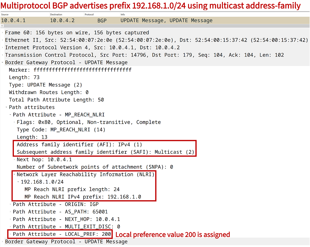
However, the RPF validation can be directly influenced using Multiprotocol-BGP (MP BGP) which is able to encapsulate and advertise multicast routes in Update messages. As a result, a BGP unicast address-family and a multicast address-family can be configured with different path preferences. This is shown in the following example.
Configuration:
R1
R1#show run | sec ^ip multi
ip multicast-routing

R1#show run | sec ^router
router bgp 65001
 bgp router-id 1.1.1.1
 bgp log-neighbor-changes
 neighbor 10.0.1.2 remote-as 65010
 neighbor 10.0.2.2 remote-as 65010
 !
 address-family ipv4
  network 192.168.1.0
  neighbor 10.0.1.2 activate
  neighbor 10.0.2.2 activate
 exit-address-family
 !
 address-family ipv4 multicast
  network 192.168.1.0
  neighbor 10.0.1.2 activate
  neighbor 10.0.2.2 activate
 exit-address-family

R1#show run int Gi0/0 | sec int
interface GigabitEthernet0/0
 description ** to Multicast Source **
 ip address 192.168.1.2 255.255.255.0
 ip pim sparse-mode
 duplex auto
 speed auto
 media-type rj45

R1#show run int Gi0/1 | sec int
interface GigabitEthernet0/1
 description ** to R2 **
 ip address 10.0.1.1 255.255.255.252
 ip pim sparse-mode
 duplex auto
 speed auto
 media-type rj45

R1#show run int Gi0/2 | sec int
interface GigabitEthernet0/2
 description ** to R3 **
 ip address 10.0.2.1 255.255.255.252
 ip pim sparse-mode
 duplex auto
 speed auto
 media-type rj45
R2
R2#show run | sec ^ip multi
ip multicast-routing

R2#show run | sec ^router
router bgp 65010
 bgp router-id 2.2.2.2
 bgp log-neighbor-changes
 neighbor 10.0.1.1 remote-as 65001
 neighbor 10.0.3.2 remote-as 65010
 !
 address-family ipv4
  neighbor 10.0.1.1 activate
  neighbor 10.0.1.1 route-map RMAP-UNICAST2 out
  neighbor 10.0.3.2 activate
  neighbor 10.0.3.2 next-hop-self
  neighbor 10.0.3.2 route-map RMAP-UNICAST1 out
 exit-address-family
 !
 address-family ipv4 multicast
  neighbor 10.0.1.1 activate
  neighbor 10.0.1.1 route-map RMAP-MULTICAST1 out
  neighbor 10.0.3.2 activate
  neighbor 10.0.3.2 next-hop-self
 exit-address-family

R2#show run | sec ^route-map
route-map RMAP-UNICAST1 permit 10
 set local-preference 200
route-map RMAP-UNICAST2 permit 10
 set metric 200
route-map RMAP-MULTICAST1 permit 10
 set metric 400

R2#show run int Gi0/0 | sec int
interface GigabitEthernet0/0
 description ** to R1 **
 ip address 10.0.1.2 255.255.255.252
 ip pim sparse-mode
 duplex auto
 speed auto
 media-type rj45

R2#show run int Gi0/1 | sec int
interface GigabitEthernet0/1
 description ** to R4 **
 ip address 10.0.3.1 255.255.255.252
 ip pim sparse-mode
 duplex auto
 speed auto
 media-type rj45
R3
R3#show run | sec ^ip multi
ip multicast-routing

R3#show run | sec ^router
router bgp 65010
 bgp router-id 3.3.3.3
 bgp log-neighbor-changes
 neighbor 10.0.2.1 remote-as 65001
 neighbor 10.0.4.2 remote-as 65010
 !
 address-family ipv4
  neighbor 10.0.2.1 activate
  neighbor 10.0.2.1 route-map RMAP-UNICAST1 out
  neighbor 10.0.4.2 activate
  neighbor 10.0.4.2 next-hop-self
 exit-address-family
 !
 address-family ipv4 multicast
  neighbor 10.0.2.1 activate
  neighbor 10.0.2.1 route-map RMAP-MULTICAST2 out
  neighbor 10.0.4.2 activate
  neighbor 10.0.4.2 next-hop-self
  neighbor 10.0.4.2 route-map RMAP-MULTICAST1 out
 exit-address-family

R3#show run | sec ^route-map
route-map RMAP-UNICAST1 permit 10
 set metric 400
route-map RMAP-MULTICAST2 permit 10
 set metric 200
route-map RMAP-MULTICAST1 permit 10
 set local-preference 200

R3#show run int Gi0/0 | sec int
interface GigabitEthernet0/0
 description ** to R1 **
 ip address 10.0.2.2 255.255.255.252
 ip pim sparse-mode
 duplex auto
 speed auto
 media-type rj45

R3#show run int Gi0/1 | sec int
interface GigabitEthernet0/1
 description ** to R4 **
 ip address 10.0.4.1 255.255.255.252
 ip pim sparse-mode
 duplex auto
 speed auto
 media-type rj45
R4
R4#show run | sec ^ip multi
ip multicast-routing

R4#show run | sec ^router
router bgp 65010
 bgp router-id 4.4.4.4
 bgp log-neighbor-changes
 neighbor 10.0.3.1 remote-as 65010
 neighbor 10.0.4.1 remote-as 65010
 neighbor 10.0.5.2 remote-as 65002
 !
 address-family ipv4
  neighbor 10.0.3.1 activate
  neighbor 10.0.3.1 next-hop-self
  neighbor 10.0.4.1 activate
  neighbor 10.0.4.1 next-hop-self
  neighbor 10.0.5.2 activate
 exit-address-family
 !
 address-family ipv4 multicast
  neighbor 10.0.3.1 activate
  neighbor 10.0.3.1 next-hop-self
  neighbor 10.0.4.1 activate
  neighbor 10.0.4.1 next-hop-self
  neighbor 10.0.5.2 activate
 exit-address-family

R4#show run int Gi0/0 | sec int
interface GigabitEthernet0/0
 description ** to R2 **
 ip address 10.0.3.2 255.255.255.252
 ip pim sparse-mode
 duplex auto
 speed auto
 media-type rj45

R4#show run int Gi0/1 | sec int
interface GigabitEthernet0/1
 description ** to R3 **
 ip address 10.0.4.2 255.255.255.252
 ip pim sparse-mode
 duplex auto
 speed auto
 media-type rj45

R4#show run int Gi0/2 | sec int
interface GigabitEthernet0/2
 description ** to R5 **
 ip address 10.0.5.1 255.255.255.252
 ip pim sparse-mode
 duplex auto
 speed auto
 media-type rj45
R5
R5#show run | sec ^ip multi
ip multicast-routing

R5#show run | sec ^ip pim
ip pim ssm range ACL-PIM-SSM

R5#show run | sec ^ip access
ip access-list standard ACL-PIM-SSM
 permit 239.0.0.1

R5#show run | sec ^router
router bgp 65002
 bgp router-id 5.5.5.5
 bgp log-neighbor-changes
 neighbor 10.0.5.1 remote-as 65010
 !
 address-family ipv4
  network 192.168.2.0
  neighbor 10.0.5.1 activate
 exit-address-family
 !
 address-family ipv4 multicast
  network 192.168.2.0
  neighbor 10.0.5.1 activate
 exit-address-family

R5#show run int Gi0/0 | sec int
interface GigabitEthernet0/0
 description ** to R4 **
 ip address 10.0.5.2 255.255.255.252
 ip pim sparse-mode
 duplex auto
 speed auto
 media-type rj45

R5#show run int Gi0/1 | sec int
interface GigabitEthernet0/1
 description ** to Multicast Receiver **
 ip address 192.168.2.2 255.255.255.0
 ip pim sparse-mode
 ip igmp version 3
 duplex auto
 speed auto
 media-type rj45
Multicast Source
Source#show run int Gi0/0 | sec int
interface GigabitEthernet0/0
 description ** to R1 **
 ip address 192.168.1.1 255.255.255.0
 duplex auto
 speed auto
 media-type rj45

Source#show run | sec ^ip route
ip route 0.0.0.0 0.0.0.0 GigabitEthernet0/0 192.168.1.2
Multicast Destination
Host#show run int Gi0/0 | sec int
interface GigabitEthernet0/0
 description ** to R5 **
 ip address 192.168.2.1 255.255.255.0
 ip igmp join-group 239.0.0.1 source 192.168.1.1
 ip igmp version 3
 duplex auto
 speed auto
 media-type rj45

Host#show run | sec ^ip route
ip route 0.0.0.0 0.0.0.0 GigabitEthernet0/0 192.168.2.2
Source#ping 239.0.0.1 re 5
Type escape sequence to abort.
Sending 5, 100-byte ICMP Echos to 239.0.0.1, timeout is 2 seconds:
Reply to request 0 from 192.168.2.1, 4 ms « Multicast stream is received on Host in Site 2
Reply to request 1 from 192.168.2.1, 4 ms
Reply to request 2 from 192.168.2.1, 5 ms
Reply to request 3 from 192.168.2.1, 4 ms
Reply to request 4 from 192.168.2.1, 4 ms
Source#trace 192.168.2.1 probe 1
Type escape sequence to abort.
Tracing the route to 192.168.2.1
VRF info: (vrf in name/id, vrf out name/id)
1 192.168.1.2 2 msec
2 10.0.1.2 2 msec « Unicast traffic chooses path through R2
3 10.0.3.2 3 msec
4 10.0.5.2 3 msec
5 192.168.2.1 4 msec
R1#mtrace 192.168.1.1 192.168.2.2 239.0.0.1
Type escape sequence to abort.
Mtrace from 192.168.1.1 to 192.168.2.2 via group 239.0.0.1
From source (?) to destination (?)
Querying full reverse path... * switching to hop-by-hop:
0 192.168.2.2
-1 * 10.0.5.2 ==> 10.0.5.2 PIM_MT [192.168.1.0/24]
-2 * 10.0.5.1 ==> 10.0.4.2 PIM_MT [192.168.1.0/24]
-3 * 10.0.4.1 ==> 10.0.2.2 PIM_MT [192.168.1.0/24] « Multicast traffic chooses path through R3
-4 * 10.0.2.1 ==> 192.168.1.2 PIM_MT [192.168.1.0/24]
-5 * Route must have changed...try again
R4#show ip rpf 192.168.1.1 239.0.0.1
RPF information for Multicast-Source (192.168.1.1)
RPF interface: GigabitEthernet0/1
RPF neighbor: R3 (10.0.4.1)
RPF route/mask: 192.168.1.0/24
RPF type: multicast (bgp 65010)« BGP is used to select the IIF on R4
Doing distance-preferred lookups across tables
RPF topology: ipv4 multicast base
R4#show ip bgp ipv4 multicast | begin Network
Network Next Hop Metric LocPrf Weight Path
*>i 192.168.1.0 10.0.4.1 0 200 0 65001 i « R4 uses neighbor R3 for the RPF interface to reach the Source
* i 10.0.3.1 0 100 0 65001 i
*> 192.168.2.0 10.0.5.2 0 0 65002 i
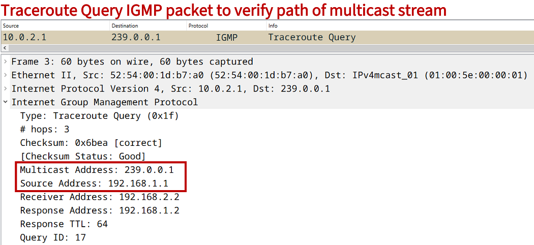
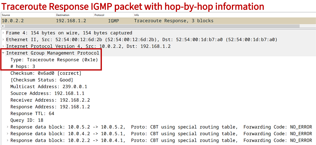
As visible in the above router outputs, unicast traffic is sent through R2 whereas traffic destined to a multicast address is transmitted through R3. Note that the mtrace command uses IGMP to encapsulate Traceroute Query and Traceroute Response packets.
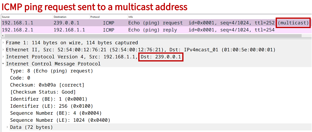
Meanwhile, the command ping 239.0.0.1 re 5 issued on the Multicast Source sends ICMP packets to the multicast address 239.0.0.1 (through R3) but the reponse packets are received as unicast through R2.
Regarding the command show ip rpf 192.168.1.1 239.0.0.1, if the IP addresses cannot be resolved to corresponding hostnames, the following output is received.
R4#show ip rpf 192.168.1.1 239.0.0.1
RPF information for ? (192.168.1.1)
  RPF interface: GigabitEthernet0/1
  RPF neighbor: ? (10.0.4.1)
  RPF route/mask: 192.168.1.0/24
  RPF type: multicast (bgp 65010)
  Doing distance-preferred lookups across tables
  RPF topology: ipv4 multicast base
Download section
Disclaimer: You download and use files from networkstudysite.com at your own risk.
Use at your own risk: networkstudysite.com makes no representations as to accuracy, completeness, currentness, suitability, or validity of any information found on this website. Full disclaimer on the About page.
Privacy Policy:
networkstudysite.com does not install browser cookies to collect or store your data.
Thank you for your interest in this blog post!
Looking for something else? View infographics, explore the archives or read the recommended posts below:


