Benefits of EtherChannel Link Aggregation with Examples
Table of Contents
Jump to section:
- • What is EtherChannel?
- • What is the difference between EtherChannel and Port-channel?
- • What is the difference between PAgP and LACP?
- • Layer-2 EtherChannel configuration
- • Layer-3 EtherChannel configuration and routed access layer design
- • Network designs that include EtherChannel link aggregation
- • Download section
- What is EtherChannel? ‹
- What is the difference between EtherChannel and Port-channel? ‹
- What is the difference between PAgP and LACP? ‹
- Layer-2 EtherChannel configuration ‹
- Layer-3 EtherChannel configuration and routed access layer design ‹
- Network designs that include EtherChannel link aggregation ‹
- Download section ‹
What is EtherChannel?
Physical ports can be aggregated to form a logical Layer-2 or Layer-3 interface using the technology called EtherChannel. An EtherChannel bundle is a group of aggregated physical interfaces on a single device. EtherChannel is a form of link aggregation, with the following benefits:
- improved fault tolerance and redundancy
- bundle has combined bandwidth of each physical link
- spanning-tree (STP) treats bundle as a single interface
- failure of a single physical link (in an EtherChannel bundle) does not trigger STP reconvergence
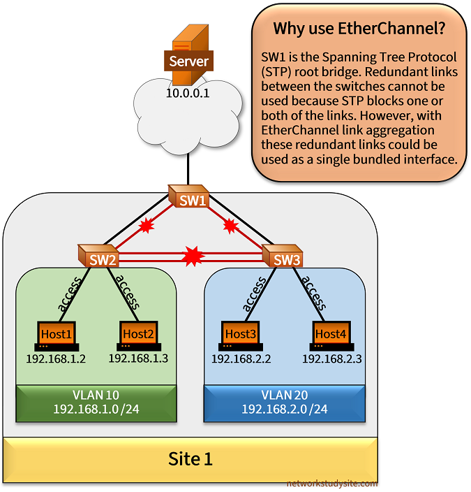
SW3#show spanning-tree vlan 20 | beg Int
Interface           Role Sts Cost      Prio.Nbr Type
------------------- ---- --- --------- -------- --------------------------------
Gi0/0               Desg FWD 4         128.1    P2p
Gi0/1               Desg FWD 4         128.2    P2p
Gi0/2               Root FWD 4         128.3    P2p
Gi0/3               Altn BLK 4         128.4    P2p
Gi1/0               Altn BLK 4         128.5    P2p
Gi1/1               Altn BLK 4         128.6    P2p


SW3#show int desc
Interface                      Status         Protocol Description
Gi0/0                          up             up       ** to Host3 **
Gi0/1                          up             up       ** to Host4 **
Gi0/2                          up             up       ** to SW1 **
Gi0/3                          up             up       ** to SW1 **
Gi1/0                          up             up       ** to SW2 **
Gi1/1                          up             up       ** to SW2 **
Gi1/2                          up             up
Gi1/3                          up             up
The above example topology describes a main problem to which EtherChannel provides a solution. SW1 is configured as the root bridge for active VLANs, and SW2 is configured as the secondary root bridge. Even though there are redundant links connecting the switches, they are not being used to their full capacity, because STP blocks one or both of the links.
What is the difference between EtherChannel and Port-channel?
EtherChannel technology enables the aggregation of multiple physical links to create a single logical interface. This logical interface is called a Port-channel interface. A Port-channel interface can either be a Layer-2 or Layer-3 interface and it represents each physical link in the bundle.
| Description | Configuration |
|---|---|
| Layer-2 port channel configured as trunk link | SW#show run int Po10 | sec int
interface Port-channel10
description ** Layer-2 Port-channel interface **
switchport trunk encapsulation dot1q
switchport mode trunk
|
| Layer-3 port channel with IPv6 address | SW#show run int Po10 | sec int
interface Port-channel10
description ** Layer-3 Port-channel interface **
no switchport
no ip address
ipv6 address FE80::1 link-local
ipv6 address 2001:DB8:2::1/64
|
What is the difference between PAgP and LACP?
Two protocols can be configured on a supported interface to dynamically negotiate an EtherChannel bundle: PAgP or LACP. PAgP is a Cisco proprietary protocol, and LACP is an open standard protocol described in the IEEE standard 802.3ad.
Layer-2 EtherChannel configuration
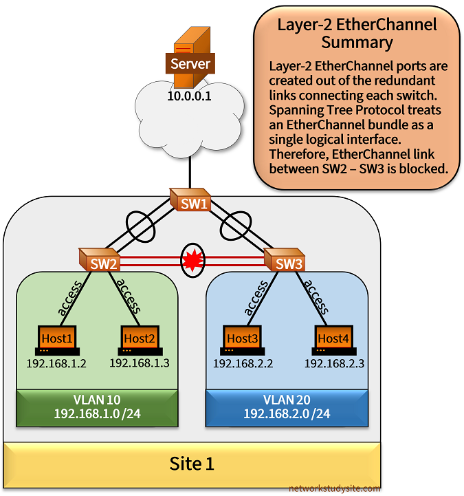
Spanning-Tree Protocol treats an EtherChannel port as a single logical link. Aggregated with EtherChannel, multiple physical links can be active between switches improving reliability and increasing overall bandwidth. EtherChannels can be configured statically (On - On), with PAgP (Desirable - Auto) or with LACP (Active - Passive). The appropriate commands are added under the physical interfaces, this automatically creates a virtual Port-channel interface and starts the negotiation process.
Configuration:
SW1
SW1#show run int Gi0/0 | sec int
interface GigabitEthernet0/0
 description ** to SW2 **
 switchport trunk allowed vlan 10,20
 switchport trunk encapsulation dot1q
 switchport mode trunk
 negotiation auto
 channel-group 10 mode on

SW1#show run int Gi0/1 | sec int
interface GigabitEthernet0/1
 description ** to SW2 **
 switchport trunk allowed vlan 10,20
 switchport trunk encapsulation dot1q
 switchport mode trunk
 negotiation auto
 channel-group 10 mode on

SW1#show run int Gi0/2 | sec int
interface GigabitEthernet0/2
 description ** to SW3 **
 switchport trunk allowed vlan 10,20
 switchport trunk encapsulation dot1q
 switchport mode trunk
 negotiation auto
 channel-group 20 mode active

SW1#show run int Gi0/3 | sec int
interface GigabitEthernet0/3
 description ** to SW3 **
 switchport trunk allowed vlan 10,20
 switchport trunk encapsulation dot1q
 switchport mode trunk
 negotiation auto
 channel-group 20 mode active

SW1#show run int Gi1/0 | sec int
interface GigabitEthernet1/0
 description ** to Server **
 no switchport
 ip address 10.0.0.2 255.255.255.252
 negotiation auto

SW1#show run int Po10 | sec int
interface Port-channel10
 description ** Layer-2 EtherChannel to SW2 **
 switchport trunk allowed vlan 10,20
 switchport trunk encapsulation dot1q
 switchport mode trunk

SW1#show run int Po20 | sec int
interface Port-channel20
 description ** Layer-2 EtherChannel to SW3 **
 switchport trunk allowed vlan 10,20
 switchport trunk encapsulation dot1q
 switchport mode trunk

SW1#show run int vlan10 | sec int
interface Vlan10
 description ** SVI default gateway for hosts in VLAN 10 **
 ip address 192.168.1.1 255.255.255.0

SW1#show run int vlan20 | sec int
interface Vlan20
 description ** SVI default gateway for hosts in VLAN 20 **
 ip address 192.168.2.1 255.255.255.0
SW2
SW2#show run int Gi0/0 | sec int
interface GigabitEthernet0/0
 description ** to SW1 **
 switchport trunk allowed vlan 10,20
 switchport trunk encapsulation dot1q
 switchport mode trunk
 negotiation auto
 channel-group 10 mode on

SW2#show run int Gi0/1 | sec int
interface GigabitEthernet0/1
 description ** to SW1 **
 switchport trunk allowed vlan 10,20
 switchport trunk encapsulation dot1q
 switchport mode trunk
 negotiation auto
 channel-group 10 mode on

SW2#show run int Gi0/2 | sec int
interface GigabitEthernet0/2
 description ** to Host1 **
 switchport access vlan 10
 switchport mode access
 negotiation auto

SW2#show run int Gi0/3 | sec int
interface GigabitEthernet0/3
 description ** to Host2 **
 switchport access vlan 10
 switchport mode access
 negotiation auto

SW2#show run int Gi1/0 | sec int
interface GigabitEthernet1/0
 description ** to SW3 **
 switchport trunk allowed vlan 10,20
 switchport trunk encapsulation dot1q
 switchport mode trunk
 negotiation auto
 channel-group 20 mode desirable

SW2#show run int Gi1/1 | sec int
interface GigabitEthernet1/1
 description ** to SW3 **
 switchport trunk allowed vlan 10,20
 switchport trunk encapsulation dot1q
 switchport mode trunk
 negotiation auto
 channel-group 20 mode desirable

SW2#show run int Po10 | sec int
interface Port-channel10
 description ** Layer-2 EtherChannel to SW1 **
 switchport trunk allowed vlan 10,20
 switchport trunk encapsulation dot1q
 switchport mode trunk

SW2#show run int Po20 | sec int
interface Port-channel20
 description ** Layer-2 EtherChannel to SW3 **
 switchport trunk allowed vlan 10,20
 switchport trunk encapsulation dot1q
 switchport mode trunk
SW3
SW3#show run int Gi0/0 | sec int
interface GigabitEthernet0/0
 description ** to Host3 **
 switchport access vlan 20
 switchport mode access
 negotiation auto

SW3#show run int Gi0/1 | sec int
interface GigabitEthernet0/1
 description ** to Host4 **
 switchport access vlan 20
 switchport mode access
 negotiation auto

SW3#show run int Gi0/2 | sec int
interface GigabitEthernet0/2
 description ** to SW1 **
 switchport trunk allowed vlan 10,20
 switchport trunk encapsulation dot1q
 switchport mode trunk
 negotiation auto
 channel-group 30 mode passive

SW3#show run int Gi0/3 | sec int
interface GigabitEthernet0/3
 description ** to SW1 **
 switchport trunk allowed vlan 10,20
 switchport trunk encapsulation dot1q
 switchport mode trunk
 negotiation auto
 channel-group 30 mode passive

SW3#show run int Gi1/0 | sec int
interface GigabitEthernet1/0
 description ** to SW2 **
 switchport trunk allowed vlan 10,20
 switchport trunk encapsulation dot1q
 switchport mode trunk
 negotiation auto
 channel-group 20 mode auto

SW3#show run int Gi1/1 | sec int
interface GigabitEthernet1/1
 description ** to SW2 **
 switchport trunk allowed vlan 10,20
 switchport trunk encapsulation dot1q
 switchport mode trunk
 negotiation auto
 channel-group 20 mode auto

SW3#show run int Po20 | sec int
interface Port-channel20
 description ** Layer-2 EtherChannel to SW2 **
 switchport trunk allowed vlan 10,20
 switchport trunk encapsulation dot1q
 switchport mode trunk

SW3#show run int Po30 | sec int
interface Port-channel30
 description ** Layer-2 EtherChannel to SW1 **
 switchport trunk allowed vlan 10,20
 switchport trunk encapsulation dot1q
 switchport mode trunk
SW1#show etherchannel summary
Flags:  D - down        P - bundled in port-channel
        I - stand-alone s - suspended
        H - Hot-standby (LACP only)
        R - Layer3      S - Layer2
        U - in use      N - not in use, no aggregation
        f - failed to allocate aggregator

        M - not in use, minimum links not met
        m - not in use, port not aggregated due to minimum links not met
        u - unsuitable for bundling
        w - waiting to be aggregated
        d - default port

        A - formed by Auto LAG


Number of channel-groups in use: 2
Number of aggregators:           2

Group  Port-channel  Protocol    Ports
------+-------------+-----------+-----------------------------------------------
10     Po10(SU)         -        Gi0/0(P)    Gi0/1(P)             « Port-Channel interface number and links in bundle
20     Po20(SU)        LACP      Gi0/2(P)    Gi0/3(P)


SW3#show pagp neighbor
Flags:  S - Device is sending Slow hello.  C - Device is in Consistent state.
        A - Device is in Auto mode.        P - Device learns on physical port.

Channel group 20 neighbors
          Partner              Partner          Partner         Partner Group
Port      Name                 Device ID        Port       Age  Flags   Cap.
Gi1/0     SW2                  5254.001e.8000   Gi1/0        9s SC      140001              « PAgP neighbors of SW3
Gi1/1     SW2                  5254.001e.8000   Gi1/1       26s SC      140001


SW3#show lacp neighbor
Flags:  S - Device is requesting Slow LACPDUs
        F - Device is requesting Fast LACPDUs
        A - Device is in Active mode       P - Device is in Passive mode

Channel group 30 neighbors

Partner's information:

                  LACP port                        Admin  Oper   Port    Port
Port      Flags   Priority  Dev ID          Age    key    Key    Number  State
Gi0/2     SA      32768     5254.001a.8000   5s    0x0    0x14   0x3     0x3D               « LACP neighbors of SW3
Gi0/3     SA      32768     5254.001a.8000  21s    0x0    0x14   0x4     0x3D


SW3#show spanning-tree vlan 20 | beg Int
Interface           Role Sts Cost      Prio.Nbr Type
------------------- ---- --- --------- -------- --------------------------------
Gi0/0               Desg FWD 4         128.1    P2p
Gi0/1               Desg FWD 4         128.2    P2p
Po30                Root FWD 3         128.65   P2p
Po20                Altn BLK 3         128.66   P2p                       « STP treats Port-Channel interface as single link
As visible in the above outputs, three different methods to establish an EtherChannel link are used between the switches in Site 1. Notice that between SW1 and SW2 LACP is configured (active - passive). The Port-Channel interface numbers do not need to match on the participating switches in order to establish an aggregate link. This is also true for aggregation with PAgP.
Moreover, on SW3 the Port-channel interface towards SW2 is blocked by STP because SW1 is the root bridge, and SW2 is the secondary root bridge. STP treats an EtherChannel bundle as a single logical interface.
The following capture shows an LACP protocol data unit (PDU). Such frames are exchanged periodically between each switch every 30 seconds if the LACP Slow Timeout is implemented. If the LACP Fast Timeout is used, then the periodic keepalive message is sent every second.
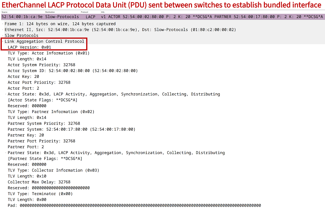
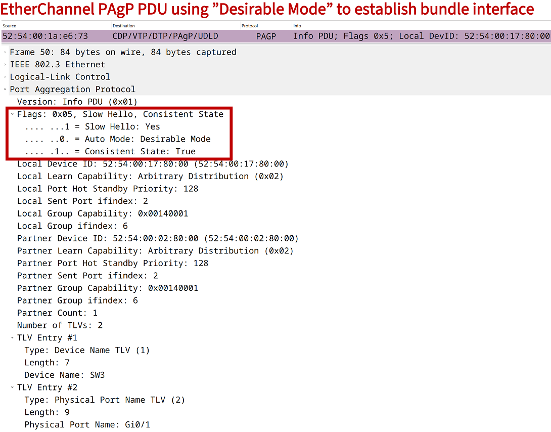
The following packet capture shows a PAgP PDU transmitted between switches using the Slow Hello setting which sends keepalives every 30 seconds. Notice how neither the PAgP nor the LACP PDU have a VLAN tag assigned. Both protocols communicate in the native VLAN.
Layer-3 EtherChannel configuration and routed access layer design
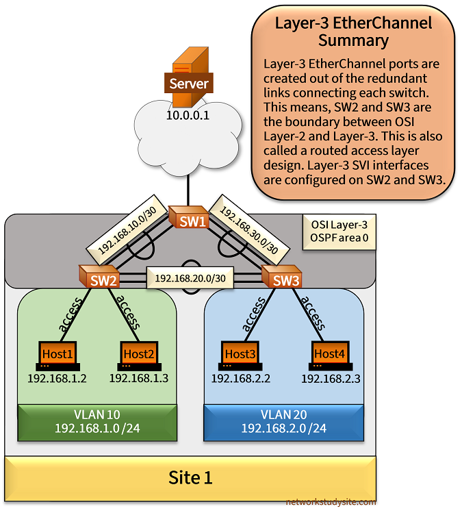
Layer-3 EtherChannel can be configured to avoid Spanning-Tree Protocol altogether. A Layer-3 Port-channel interface has an IP address assigned and participates in IP routing. This is achieved by adding the command no switchport to the physical interfaces before assigning them to a common channel-group bundle. As a result, the created Port-channel interface will become a Layer-3 interface and an IP address can be assigned.
In the following scenario, the link aggregation interfaces have IP addresses, and OSPF is configured between the switches. This also enables IP routing features, such as ECMP/Loadsharing. Meanwhile, the hosts use the SVI interfaces configured on SW2 and SW3 as their default gateway. Specifically, SW2 has SVI VLAN 10 with gateway IP 192.168.1.1, and SW3 has SVI VLAN 20 with IP 192.168.2.1 assigned.
Configuration:
SW1
SW1#show run int Gi0/0 | sec int
interface GigabitEthernet0/0
 description ** to SW2 **
 no switchport
 no ip address
 negotiation auto
 channel-group 10 mode on

SW1#show run int Gi0/1 | sec int
interface GigabitEthernet0/1
 description ** to SW2 **
 no switchport
 no ip address
 negotiation auto
 channel-group 10 mode on

SW1#show run int Gi0/2 | sec int
interface GigabitEthernet0/2
 description ** to SW3 **
 no switchport
 no ip address
 negotiation auto
 channel-group 20 mode on

SW1#show run int Gi0/3 | sec int
interface GigabitEthernet0/3
 description ** to SW3 **
 no switchport
 no ip address
 negotiation auto
 channel-group 20 mode on

SW1#show run int Gi1/0 | sec int
interface GigabitEthernet1/0
 description ** to Server **
 no switchport
 ip address 10.0.0.2 255.255.255.252
 negotiation auto

SW1#show run int Po10 | sec int
interface Port-channel10
 description ** Layer-3 EtherChannel to SW2 **
 no switchport
 ip address 192.168.10.1 255.255.255.252
 ip ospf network point-to-point

SW1#show run int Po20 | sec int
interface Port-channel20
 description ** Layer-3 EtherChannel to SW3 **
 no switchport
 ip address 192.168.30.1 255.255.255.252
 ip ospf network point-to-point

SW1#show run | sec ^router
router ospf 10
 router-id 1.1.1.1
 network 192.168.10.0 0.0.0.3 area 0
 network 192.168.30.0 0.0.0.3 area 0
 default-information originate always
SW2
SW2#show run int Gi0/0 | sec int
interface GigabitEthernet0/0
 description ** to SW1 **
 no switchport
 no ip address
 negotiation auto
 channel-group 10 mode on

SW2#show run int Gi0/1 | sec int
interface GigabitEthernet0/1
 description ** to SW1 **
 no switchport
 no ip address
 negotiation auto
 channel-group 10 mode on

SW2#show run int Gi0/2 | sec int
interface GigabitEthernet0/2
 description ** to Host1 **
 switchport access vlan 10
 switchport mode access
 negotiation auto

SW2#show run int Gi0/3 | sec int
interface GigabitEthernet0/3
 description ** to Host2 **
 switchport access vlan 10
 switchport mode access
 negotiation auto

SW2#show run int Gi1/0 | sec int
interface GigabitEthernet1/0
 description ** to SW3 **
 no switchport
 no ip address
 negotiation auto
 channel-group 20 mode on

SW2#show run int Gi1/1 | sec int
interface GigabitEthernet1/1
 description ** to SW3 **
 no switchport
 no ip address
 negotiation auto
 channel-group 20 mode on

SW2#show run int Po10 | sec int
interface Port-channel10
 description ** Layer-3 EtherChannel to SW1 **
 no switchport
 ip address 192.168.10.2 255.255.255.252
 ip ospf network point-to-point

SW2#show run int Po20 | sec int
interface Port-channel20
 description ** Layer-3 EtherChannel to SW3 **
 no switchport
 ip address 192.168.20.1 255.255.255.252
 ip ospf network point-to-point

SW2#show run int vlan 10 | sec int
interface Vlan10
 description ** SVI default gateway for hosts in VLAN 10 **
 ip address 192.168.1.1 255.255.255.0

SW2#show run | sec ^router
router ospf 10
 router-id 2.2.2.2
 network 192.168.1.0 0.0.0.255 area 0
 network 192.168.10.0 0.0.0.3 area 0
 network 192.168.20.0 0.0.0.3 area 0
SW3
SW3#show run int Gi0/0 | sec int
interface GigabitEthernet0/0
 description ** to Host3 **
 switchport access vlan 20
 switchport mode access
 negotiation auto

SW3#show run int Gi0/1 | sec int
interface GigabitEthernet0/1
 description ** to Host4 **
 switchport access vlan 20
 switchport mode access
 negotiation auto

SW3#show run int Gi0/2 | sec int
interface GigabitEthernet0/2
 description ** to SW1 **
 no switchport
 no ip address
 negotiation auto
 channel-group 10 mode on

SW3#show run int Gi0/3 | sec int
interface GigabitEthernet0/3
 description ** to SW1 **
 no switchport
 no ip address
 negotiation auto
 channel-group 10 mode on

SW3#show run int Gi1/0 | sec int
interface GigabitEthernet1/0
 description ** to SW2 **
 no switchport
 no ip address
 negotiation auto
 channel-group 20 mode on

SW3#show run int Gi1/1 | sec int
interface GigabitEthernet1/1
 description ** to SW2 **
 no switchport
 no ip address
 negotiation auto
 channel-group 20 mode on

SW3#show run int Po10 | sec int
interface Port-channel10
 description ** Layer-3 EtherChannel to SW1 **
 no switchport
 ip address 192.168.30.2 255.255.255.252
 ip ospf network point-to-point

SW3#show run int Po20 | sec int
interface Port-channel20
 description ** Layer-3 EtherChannel to SW2 **
 no switchport
 ip address 192.168.20.2 255.255.255.252
 ip ospf network point-to-point

SW3#show run int vlan 20 | sec int
interface Vlan20
 description ** SVI default gateway for hosts in VLAN 20 **
 ip address 192.168.2.1 255.255.255.0

SW3#show run | sec ^router
router ospf 10
 router-id 3.3.3.3
 network 192.168.2.0 0.0.0.255 area 0
 network 192.168.20.0 0.0.0.3 area 0
 network 192.168.30.0 0.0.0.3 area 0
Host1
Host1#show run int Gi0/0 | sec int
interface GigabitEthernet0/0
 description ** to SW2 **
 ip address 192.168.1.2 255.255.255.0
 duplex auto
 speed auto
 media-type rj45

Host1#show run | sec ^ip route
ip route 0.0.0.0 0.0.0.0 192.168.1.1
SW1#show ip ospf neighbor

Neighbor ID     Pri   State           Dead Time   Address         Interface
3.3.3.3           0   FULL/  -        00:00:32    192.168.30.2    Port-channel20         « OSPF neighborship created on Port-Channel interface
2.2.2.2           0   FULL/  -        00:00:35    192.168.10.2    Port-channel10


SW1#show ip route ospf | beg Ga
Gateway of last resort is not set

O     192.168.1.0/24 [110/2] via 192.168.10.2, 01:02:43, Port-channel10       « Prefix of VLAN 10 learned on SW1 with OSPF
O     192.168.2.0/24 [110/2] via 192.168.30.2, 00:44:36, Port-channel20
      192.168.20.0/30 is subnetted, 1 subnets
O        192.168.20.0 [110/2] via 192.168.30.2, 00:44:36, Port-channel20
                      [110/2] via 192.168.10.2, 01:02:53, Port-channel10


SW2#show ip route ospf | beg Ga
Gateway of last resort is 192.168.10.1 to network 0.0.0.0

O*E2  0.0.0.0/0 [110/1] via 192.168.10.1, 00:03:03, Port-channel10            « SW2 receives OSPF default route from SW1
O     192.168.2.0/24 [110/2] via 192.168.20.2, 00:45:12, Port-channel20
      192.168.30.0/30 is subnetted, 1 subnets
O        192.168.30.0 [110/2] via 192.168.20.2, 00:45:12, Port-channel20
                      [110/2] via 192.168.10.1, 01:03:37, Port-channel10


SW1#show etherchannel summary
Flags:  D - down        P - bundled in port-channel
        I - stand-alone s - suspended
        H - Hot-standby (LACP only)
        R - Layer3      S - Layer2
        U - in use      N - not in use, no aggregation
        f - failed to allocate aggregator

        M - not in use, minimum links not met
        m - not in use, port not aggregated due to minimum links not met
        u - unsuitable for bundling
        w - waiting to be aggregated
        d - default port

        A - formed by Auto LAG


Number of channel-groups in use: 2
Number of aggregators:           2

Group  Port-channel  Protocol    Ports
------+-------------+-----------+-----------------------------------------------
10     Po10(RU)         -        Gi0/0(P)    Gi0/1(P)                      « Routed Layer-3 EtherChannel created and in use
20     Po20(RU)         -        Gi0/2(P)    Gi0/3(P)


Host1#trace 192.168.2.3 probe 1
Type escape sequence to abort.
Tracing the route to 192.168.2.3
VRF info: (vrf in name/id, vrf out name/id)
  1 192.168.1.1 2 msec                    « This is the SVI VLAN 10 on SW1
  2 192.168.20.2 3 msec                   « This is the SW3 Port-Channel interface IP
  3 192.168.2.3 3 msec


Host1#trace 10.0.0.1 probe 1
Type escape sequence to abort.
Tracing the route to 10.0.0.1
VRF info: (vrf in name/id, vrf out name/id)
  1 192.168.1.1 2 msec
  2 192.168.10.1 3 msec                   « This is the SW1 Port-Channel interface IP
  3 10.0.0.1 25 msec
Network designs that include EtherChannel link aggregation
EtherChannel link aggregation is deployed together with EVPN multihoming on the Provider Edge (PE) routers to create a single Layer-2 virtual interface. As a result, a Customer Edge (CE) device can be physically connected to different PE routers in a redundant design.
Another example of EtherChannel is with the Service Provider technology Q-in-Q (double-tagging frames). Customer sites can implement a redundant connection with the Service Provider Q-in-Q edge devices (PE) by deploying EtherChannel link aggregation. This is made possible because Q-in-Q supports Layer-2 Protocol Tunneling (L2PT).