Introduction to VLAN Tagging, Bridging and Trunk Links
Table of Contents
- What is an 802.1Q trunk? ‹
- Inter-VLAN routing with SVI explained ‹
- Understanding bridged interfaces BVI and BDI ‹
- Dynamic (DTP) and static trunking comparison ‹
- VLAN double-tagged frame with Q-in-Q ‹
- Download section ‹
What is an 802.1Q trunk?
802.1Q is a networking standard that outlines the technology behind Virtual Local Area Networks (VLAN). This standard is also referred to as Dot1q, and defines how Ethernet frames can insert a 32-bit tag containing a 12-bit VLAN Identifier (VID) field. Thus, Ethernet frames are capable of carrying information for various VLANs by inserting VLAN tags. The following packet capture shows a tagged frame with the VLAN ID 10.
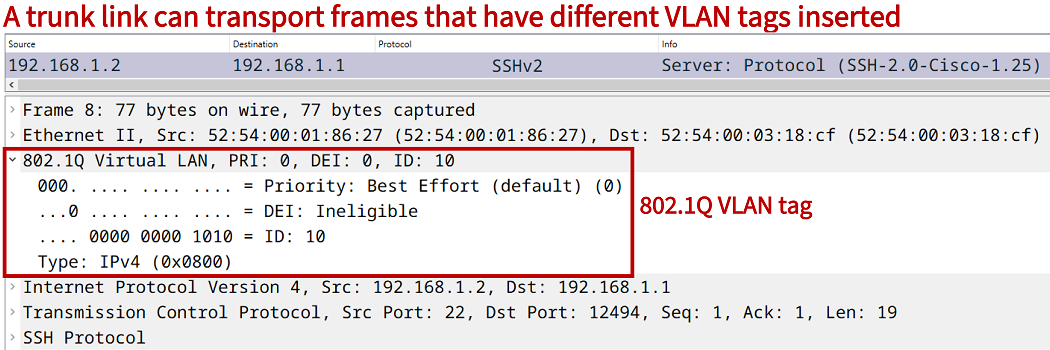
As a result, two types of ports are differentiated. On the one side, there are ports that carry traffic for only a single VLAN, these are called access ports. On the other side, there are ports that carry traffic for multiple VLANs, these are called trunk ports, trunk links or trunks.
Inter-VLAN routing with SVI explained
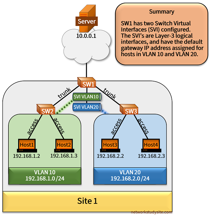
In the following example topology Site 1 has two VLANs configured, VLAN 10 and VLAN 20. To reach the Server in an external network, the hosts in Site 1 use SW1 as their default gateway. Specifically, SW1 is a Layer-3 switch and has a Switch Virtual Interface (SVI) configured for each VLAN. The SVI is a logical Layer-3 interface with an IP address assigned, and can be used as the default gateway address for the hosts.
The following are important aspects related to SVI.
- After configuring a VLAN interface (SVI) it is in the shutdown state, and the no shutdown command needs to be issued. For an SVI to be in the Up/Up state, the associated VLAN needs to be active on the local device including a Layer-2 interface in the STP forwarding state carrying traffic for the SVI VLAN. This is also called autostate.
- SVI enables an effective way of routing between VLANs on network devices with a high port density. Configuring an SVI is a scalable approach to enabling internal and external LAN connectivity on a single device in comparison to using subinterfaces on a router (ROAS).
- Routing protocol failure detection and convergence times are slower when a session (neighbor adjacency) is established between SVIs in comparison to using routed Layer-3 interfaces.
Configuration:
SW1
SW1#show run int vlan10 | sec int
interface Vlan10
 description ** SVI default gateway for hosts in VLAN 10 **
 ip address 192.168.1.1 255.255.255.0

SW1#show run int vlan20 | sec int
interface Vlan20
 description ** SVI default gateway for hosts in VLAN 20 **
 ip address 192.168.2.1 255.255.255.0

SW1#show run int Gi0/0 | sec int
interface GigabitEthernet0/0
 description ** to Server **
 no switchport
 ip address 10.0.0.2 255.255.255.0
 negotiation auto

SW1#show run int Gi0/1 | sec int
interface GigabitEthernet0/1
 description ** trunk link to SW2 **
 switchport trunk allowed vlan 10
 switchport trunk encapsulation dot1q
 switchport mode trunk
 negotiation auto

SW1#show run int Gi0/2 | sec int
interface GigabitEthernet0/2
 description ** trunk link to SW3 **
 switchport trunk allowed vlan 20
 switchport trunk encapsulation dot1q
 switchport mode trunk
 negotiation auto
SW2
SW2#show run int Gi0/0 | sec int
interface GigabitEthernet0/0
 description ** trunk link to SW1 **
 switchport trunk allowed vlan 10
 switchport trunk encapsulation dot1q
 switchport mode trunk
 negotiation auto

SW2#show run int Gi0/1 | sec int
interface GigabitEthernet0/1
 description ** access port to Host1 **
 switchport access vlan 10
 switchport mode access
 negotiation auto

SW2#show run int Gi0/2 | sec int
interface GigabitEthernet0/2
 description ** access port to Host2 **
 switchport access vlan 10
 switchport mode access
 negotiation auto
SW3
SW3#show run int Gi0/0 | sec int
interface GigabitEthernet0/0
 description ** trunk link to SW1 **
 switchport trunk allowed vlan 20
 switchport trunk encapsulation dot1q
 switchport mode trunk
 negotiation auto

SW3#show run int Gi0/1 | sec int
interface GigabitEthernet0/1
 description ** access port to Host3 **
 switchport access vlan 20
 switchport mode access
 negotiation auto

SW3#show run int Gi0/2 | sec int
interface GigabitEthernet0/2
 description ** access port to Host4 **
 switchport access vlan 20
 switchport mode access
 negotiation auto
Host1
Host1#show run int Gi0/0 | sec int
interface GigabitEthernet0/0
 description ** to SW2 **
 ip address 192.168.1.2 255.255.255.0
 duplex auto
 speed auto
 media-type rj45

Host1#show run | sec ^ip route
ip route 0.0.0.0 0.0.0.0 192.168.1.1
Server
Server#show run int Gi0/0 | sec int
interface GigabitEthernet0/0
 description ** to SW1 **
 ip address 10.0.0.1 255.255.255.0
 duplex auto
 speed auto
 media-type rj45

Server#show run | sec ^ip route
ip route 0.0.0.0 0.0.0.0 10.0.0.2
SW1#show ip int br
Interface              IP-Address      OK? Method Status                Protocol
GigabitEthernet0/0     10.0.0.2        YES manual up                    up
GigabitEthernet0/1     unassigned      YES unset  up                    up
GigabitEthernet0/2     unassigned      YES unset  up                    up
GigabitEthernet0/3     unassigned      YES unset  up                    up
Vlan10                 192.168.1.1     YES manual up                    up       « SVI for VLAN 10 with default gateway IP address
Vlan20                 192.168.2.1     YES manual up                    up


Host1#ping 192.168.1.3
Type escape sequence to abort.
Sending 5, 100-byte ICMP Echos to 192.168.1.3, timeout is 2 seconds:
!!!!!
Success rate is 100 percent (5/5), round-trip min/avg/max = 2/2/2 ms             « Intra-VLAN switching within VLAN 10 works


Host1#ping 192.168.2.3
Type escape sequence to abort.
Sending 5, 100-byte ICMP Echos to 192.168.2.3, timeout is 2 seconds:
!!!!!
Success rate is 100 percent (5/5), round-trip min/avg/max = 4/4/6 ms             « Inter-VLAN routing between VLAN 10 and 20 works


Host1#trace 192.168.2.3 probe 1
Type escape sequence to abort.
Tracing the route to 192.168.2.3
VRF info: (vrf in name/id, vrf out name/id)
  1 192.168.1.1 2 msec                                « SVI is used to route traffic between VLANs
  2 192.168.2.3 5 msec
Understanding bridged interfaces BVI and BDI
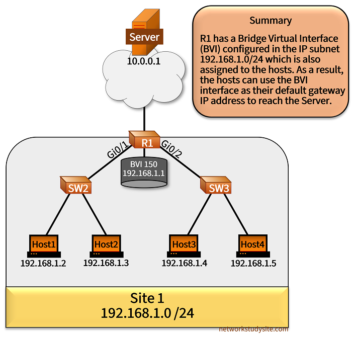
In the following example scenario, R1 uses a Bridge Virtual Interface (BVI) to assign a default gateway IP address used by the hosts in Site 1. The R1 interface Gi0/1 and Gi0/2 are Layer-3 routed interfaces which are configured with the command bridge-group 150. This command enables R1 interface Gi0/1 and Gi0/2 to be in the same broadcast domain, and bridge traffic destined to the Layer-3 BVI.
Configuration:
R1
R1#show run | sec ^bridge
bridge irb
bridge 150 protocol ieee
bridge 150 route ip

R1#show run int Gi0/0 | sec int
interface GigabitEthernet0/0
 description ** to Server **
 ip address 10.0.0.2 255.255.255.0
 duplex auto
 speed auto
 media-type rj45

R1#show run int Gi0/1 | sec int
interface GigabitEthernet0/1
 description ** to SW2 **
 no ip address
 duplex auto
 speed auto
 media-type rj45
 bridge-group 150

R1#show run int Gi0/2 | sec int
interface GigabitEthernet0/2
 description ** to SW3 **
 no ip address
 duplex auto
 speed auto
 media-type rj45
 bridge-group 150

R1#show run int BVI 150 | sec int
interface BVI150
 description ** Bridge Virtual Interface **
 ip address 192.168.1.1 255.255.255.0
SW2
SW1#show run int Gi0/0 | sec int
interface GigabitEthernet0/0
 description ** trunk link to R1 **
 switchport trunk encapsulation dot1q
 switchport mode trunk
 negotiation auto

SW1#show run int Gi0/1 | sec int
interface GigabitEthernet0/1
 description ** access port to Host1 **
 switchport mode access
 negotiation auto

SW1#show run int Gi0/2 | sec int
interface GigabitEthernet0/2
 description ** access port to Host2 **
 switchport mode access
 negotiation auto
SW3
SW2#show run int Gi0/0 | sec int
interface GigabitEthernet0/0
 description ** trunk link to R1 **
 switchport trunk encapsulation dot1q
 switchport mode trunk
 negotiation auto

SW2#show run int Gi0/1 | sec int
interface GigabitEthernet0/1
 description ** access port to Host3 **
 switchport mode access
 negotiation auto

SW2#show run int Gi0/2 | sec int
interface GigabitEthernet0/2
 description ** access port to Host4 **
 switchport mode access
 negotiation auto
Host1
R2#show run int Gi0/0 | sec int
interface GigabitEthernet0/0
 description ** to R1 **
 ip address 192.168.1.2 255.255.255.0
 duplex auto
 speed auto
 media-type rj45

R2#show run | sec ^ip route
ip route 0.0.0.0 0.0.0.0 192.168.1.1
R1#show ip int brief
Interface                  IP-Address      OK? Method Status                Protocol
GigabitEthernet0/0         10.0.0.2        YES NVRAM  up                    up
GigabitEthernet0/1         unassigned      YES NVRAM  up                    up
GigabitEthernet0/2         unassigned      YES NVRAM  up                    up
GigabitEthernet0/3         unassigned      YES NVRAM  administratively down down
BVI150                     192.168.1.1     YES manual up                    up           « R1 BVI is Up/Up


Host1#ping 10.0.0.1
Type escape sequence to abort.
Sending 5, 100-byte ICMP Echos to 10.0.0.1, timeout is 2 seconds:
!!!!!
Success rate is 100 percent (5/5), round-trip min/avg/max = 25/25/26 ms                  « Host1 can reach the Server through R1


Host1#trace 10.0.0.1 probe 1
Type escape sequence to abort.
Tracing the route to 10.0.0.1
VRF info: (vrf in name/id, vrf out name/id)
  1 192.168.1.1 3 msec                           « Host1 uses the default gateway IP address configured on R1 BVI
  2 10.0.0.1 24 msec


Host1#ping 192.168.1.5
Type escape sequence to abort.
Sending 5, 100-byte ICMP Echos to 192.168.1.5, timeout is 2 seconds:
!!!!!
Success rate is 100 percent (5/5), round-trip min/avg/max = 3/4/5 ms                       « R1 also bridges traffic within the same VLAN


R1#show arp
Protocol  Address          Age (min)  Hardware Addr   Type   Interface
Internet  10.0.0.1              236   5254.0007.533f  ARPA   GigabitEthernet0/0
Internet  10.0.0.2                -   5254.0017.b5b3  ARPA   GigabitEthernet0/0
Internet  192.168.1.1             -   5254.001d.9017  ARPA   BVI150
Internet  192.168.1.2            10   5254.0015.7f0a  ARPA   BVI150                         « R1 learns ARP entries through BVI interface
Internet  192.168.1.3           158   5254.0002.854d  ARPA   BVI150
Internet  192.168.1.4             8   5254.0014.04f6  ARPA   BVI150
Internet  192.168.1.5           159   5254.001b.003f  ARPA   BVI150
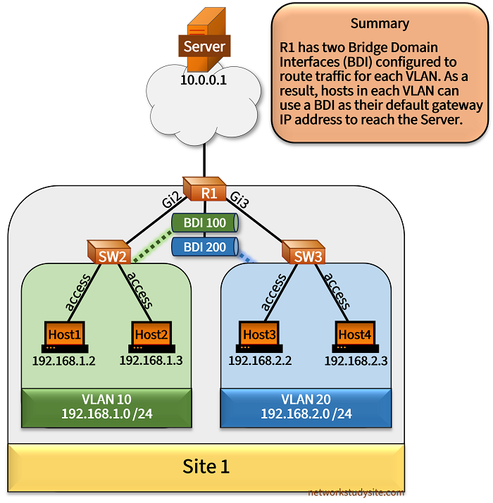
In the example shown below, R1 is configured with Bridge Domain Interface (BDI) 100 and 200. The BDI interfaces are assigned with default gateway IP addresses used by hosts in VLAN 10 and VLAN 20. Under the Layer-3 routed interface Gi2 and Gi3 the Service Instance 50 and 55 are configured and connected to Bridge-Domain 100 and 200 respectively. The Service Instance is used by the BDI in each VLAN to receive IP traffic from the hosts.
Moreover, static routes are configured to enable inter-VLAN routing on R1 in addition to enabling connectivity to the Server in the external network. Thus, R1 provides integrated routing and bridging (IRB) services for hosts in Site 1.
Configuration:
R1
R1#show run int Gi1 | sec int
interface GigabitEthernet1
 description ** to Server **
 ip address 10.0.0.2 255.255.255.0
 negotiation auto
 no mop enabled
 no mop sysid

R1#show run int Gi2 | sec int
interface GigabitEthernet2
 description ** to SW2 **
 no ip address
 negotiation auto
 no mop enabled
 no mop sysid
 service instance 50 ethernet
  encapsulation dot1q 10
  bridge-domain 100
 !

R1#show run int Gi3 | sec int
interface GigabitEthernet3
 description ** to SW3 **
 no ip address
 negotiation auto
 no mop enabled
 no mop sysid
 service instance 55 ethernet
  encapsulation dot1q 20
  bridge-domain 200
 !

R1#show run int BDI 100 | sec int
interface BDI100
 description ** Bridge Domain Interface for VLAN 10 **
 ip address 192.168.1.1 255.255.255.0
 encapsulation dot1Q 10
 no mop enabled
 no mop sysid

R1#show run int BDI 200 | sec int
interface BDI200
 description ** Bridge Domain Interface for VLAN 20 **
 ip address 192.168.2.1 255.255.255.0
 encapsulation dot1Q 20
 no mop enabled
 no mop sysid

R1#show run | sec ^ip route
ip route 192.168.1.0 255.255.255.0 BDI100
ip route 192.168.2.0 255.255.255.0 BDI200
SW2
SW2#show run int Gi0/0 | sec int
interface GigabitEthernet0/0
 description ** trunk link to SW1 **
 switchport trunk allowed vlan 10
 switchport trunk encapsulation dot1q
 switchport mode trunk
 negotiation auto

SW2#show run int Gi0/1 | sec int
interface GigabitEthernet0/1
 description ** access port to Host1 **
 switchport access vlan 10
 switchport mode access
 negotiation auto

SW2#show run int Gi0/2 | sec int
interface GigabitEthernet0/2
 description ** access port to Host2 **
 switchport access vlan 10
 switchport mode access
 negotiation auto
SW3
SW3#show run int Gi0/0 | sec int
interface GigabitEthernet0/0
 description ** trunk link to SW1 **
 switchport trunk allowed vlan 20
 switchport trunk encapsulation dot1q
 switchport mode trunk
 negotiation auto

SW3#show run int Gi0/1 | sec int
interface GigabitEthernet0/1
 description ** access port to Host3 **
 switchport access vlan 20
 switchport mode access
 negotiation auto

SW3#show run int Gi0/2 | sec int
interface GigabitEthernet0/2
 description ** access port to Host4 **
 switchport access vlan 20
 switchport mode access
 negotiation auto
Host1
Host1#show run int Gi0/0 | sec int
interface GigabitEthernet0/0
 description ** to R1 **
 ip address 192.168.1.2 255.255.255.0
 duplex auto
 speed auto
 media-type rj45

Host1#show run | sec ^ip route
ip route 0.0.0.0 0.0.0.0 192.168.1.1
R1#show ip int brief
Interface              IP-Address      OK? Method Status                Protocol
GigabitEthernet1       10.0.0.2        YES NVRAM  up                    up
GigabitEthernet2       unassigned      YES NVRAM  up                    up
GigabitEthernet3       unassigned      YES NVRAM  up                    up
GigabitEthernet4       unassigned      YES NVRAM  administratively down down
BDI100                 192.168.1.1     YES NVRAM  up                    up             « BDI interface in Up/Up status on R1
BDI200                 192.168.2.1     YES NVRAM  up                    up


Host1#ping 10.0.0.1
Type escape sequence to abort.
Sending 5, 100-byte ICMP Echos to 10.0.0.1, timeout is 2 seconds:
!!!!!
Success rate is 100 percent (5/5), round-trip min/avg/max = 24/24/25 ms                « Host1 can reach external Server


Host1#ping 192.168.2.3
Type escape sequence to abort.
Sending 5, 100-byte ICMP Echos to 192.168.2.3, timeout is 2 seconds:
!!!!!
Success rate is 100 percent (5/5), round-trip min/avg/max = 3/3/4 ms                   « Host1 can reach Host4 throug R1 inter-VLAN routing


Host1#trace 192.168.2.3 probe 1
Type escape sequence to abort.
Tracing the route to 192.168.2.3
VRF info: (vrf in name/id, vrf out name/id)
  1 192.168.1.1 3 msec                                « R1 BDI interface 100 default gateway IP address for VLAN 10
  2 192.168.2.3 5 msec


R1#show arp
Protocol  Address          Age (min)  Hardware Addr   Type   Interface
Internet  10.0.0.1              128   5254.000b.4977  ARPA   GigabitEthernet1
Internet  10.0.0.2                -   5254.0008.1ae1  ARPA   GigabitEthernet1
Internet  192.168.1.1             -   001e.7a45.c9bf  ARPA   BDI100              « ARP displays BDI interface
Internet  192.168.1.2           172   5254.001a.603e  ARPA   BDI100
Internet  192.168.1.3             0   5254.001a.eb0e  ARPA   BDI100
Internet  192.168.2.1             -   001e.7a45.c9bf  ARPA   BDI200
Internet  192.168.2.2           137   5254.0009.8f9a  ARPA   BDI200
Internet  192.168.2.3           113   5254.000f.64cb  ARPA   BDI200


R1#show bridge-domain 100
Bridge-domain 100 (2 ports in all)
State: UP                    Mac learning: Enabled
Aging-Timer: 300 second(s)
Maximum address limit: 65536
    BDI100  (up)
    GigabitEthernet2 service instance 50
   AED MAC address    Policy  Tag       Age  Pseudoport
   0   5254.001A.603E forward dynamic   248  GigabitEthernet2.EFP50             « EFP is Ethernet Flow Point created by Service Instance
   -   001E.7A45.C9BF to_bdi  static    0    BDI100
   0   5254.001A.EB0E forward dynamic   279  GigabitEthernet2.EFP50


R1#show bridge-domain 200
Bridge-domain 200 (2 ports in all)
State: UP                    Mac learning: Enabled
Aging-Timer: 300 second(s)
Maximum address limit: 65536
    BDI200  (up)
    GigabitEthernet3 service instance 55
   AED MAC address    Policy  Tag       Age  Pseudoport
   0   5254.000F.64CB forward dynamic   277  GigabitEthernet3.EFP55
   0   5254.0009.8F9A forward dynamic   297  GigabitEthernet3.EFP55
   -   001E.7A45.C9BF to_bdi  static    0    BDI200
As visible in the above Bridge-Domain outputs, an Ethernet Flow Point (EFP) is created on the physical Layer-3 routed interface that is configured with a Service Instance. This is important because an EFP identifies the processing characteristics of frames received on the physical port. For example, the EFP on R1 connects the Service Instance with the Bridge-Domain in VLAN 10. This enables the BDI interface to receive IP traffic in VLAN 10.
Dynamic (DTP) and static trunking comparison
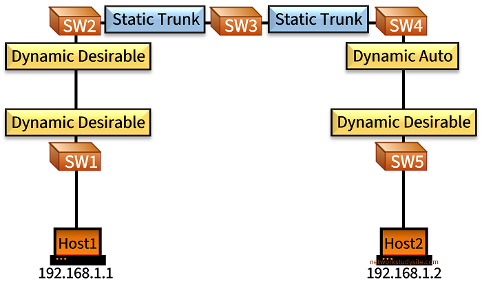
In the following scenario Host1 and Host2 are connected in VLAN 10 using the IP subnet 192.168.1.0/24. The switches in between Host1 and Host2 have trunk links configured in various ways. Dynamic Trunking Protocol (DTP) is used between SW1-SW2 and between SW4-SW5 to negotiate a trunk link. DTP is not implemented between SW2-SW3-SW4, and instead static trunks are configured between these switches.
Configuration:
SW1
SW1#show run int Gi0/0 | sec int
interface GigabitEthernet0/0
 description ** to Host1 **
 switchport access vlan 10
 switchport mode access
 negotiation auto

SW1#show run int Gi0/1 | sec int
interface GigabitEthernet0/1
 description ** to SW2 **
 switchport trunk allowed vlan 10
 switchport trunk encapsulation dot1q
 switchport mode dynamic desirable
 negotiation auto
SW2
SW2#show run int Gi0/0 | sec int
interface GigabitEthernet0/0
 description ** to SW1 **
 switchport trunk allowed vlan 10
 switchport trunk encapsulation dot1q
 switchport mode dynamic desirable
 negotiation auto

SW2#show run int Gi0/1 | sec int
interface GigabitEthernet0/1
 description ** to SW3 **
 switchport trunk allowed vlan 10
 switchport trunk encapsulation dot1q
 switchport mode trunk
 negotiation auto
SW3
SW3#show run int Gi0/0 | sec int
interface GigabitEthernet0/0
 description ** to SW2 **
 switchport trunk allowed vlan 10
 switchport trunk encapsulation dot1q
 switchport mode trunk
 negotiation auto

SW3#show run int Gi0/1 | sec int
interface GigabitEthernet0/1
 description ** to SW4 **
 switchport trunk allowed vlan 10
 switchport trunk encapsulation dot1q
 switchport mode trunk
 negotiation auto
SW4
SW4#show run int Gi0/0 | sec int
interface GigabitEthernet0/0
 description ** to SW5 **
 switchport trunk allowed vlan 10
 switchport trunk encapsulation dot1q
 negotiation auto

SW4#show run int Gi0/1 | sec int
interface GigabitEthernet0/1
 description ** to SW3 **
 switchport trunk allowed vlan 10
 switchport trunk encapsulation dot1q
 switchport mode trunk
 negotiation auto
SW5
SW5#show run int Gi0/0 | sec int
interface GigabitEthernet0/0
 description ** to Host2 **
 switchport access vlan 10
 switchport mode access
 negotiation auto

SW5#show run int Gi0/1 | sec int
interface GigabitEthernet0/1
 description ** to SW4 **
 switchport trunk allowed vlan 10
 switchport trunk encapsulation dot1q
 switchport mode dynamic desirable
 negotiation auto
Host1
Host1#show run int Gi0/0 | sec int
interface GigabitEthernet0/0
 description ** to SW1 **
 ip address 192.168.1.1 255.255.255.0
 duplex auto
 speed auto
 media-type rj45
SW1#show dtp interface Gi0/1
DTP information for GigabitEthernet0/1:
  TOS/TAS/TNS:                              TRUNK/DESIRABLE/TRUNK          « DTP Dynamic Desirable is configured
  TOT/TAT/TNT:                              802.1Q/802.1Q/802.1Q
  Neighbor address 1:                       5254001E6A27
  Neighbor address 2:                       000000000000
  Hello timer expiration (sec/state):       13/RUNNING                     « DTP Hello timer is 30 seconds
  Access timer expiration (sec/state):      283/RUNNING
  Negotiation timer expiration (sec/state): never/STOPPED
  Multidrop timer expiration (sec/state):   never/STOPPED
  FSM state:                                S6:TRUNK
  # times multi & trunk                     0
  Enabled:                                  yes
  In STP:                                   no

  Statistics
  ----------
  103 packets received (103 good)
  0 packets dropped
      0 nonegotiate, 0 bad version, 0 domain mismatches,
      0 bad TLVs, 0 bad TAS, 0 bad TAT, 0 bad TOT, 0 other
  119 packets output (119 good)
      101 native, 18 software encap isl, 0 isl hardware native
  0 output errors
  0 trunk timeouts
  1 link ups, last link up on Wed May 22 2024, 15:29:37
  0 link downs


SW1#show int Gi0/1 switchport
Name: Gi0/1
Switchport: Enabled
Administrative Mode: dynamic desirable
Operational Mode: trunk                                  « DTP negotiation creates trunk link
Administrative Trunking Encapsulation: dot1q
Operational Trunking Encapsulation: dot1q
Negotiation of Trunking: On
Access Mode VLAN: 1 (default)
Trunking Native Mode VLAN: 1 (default)
Administrative Native VLAN tagging: enabled
Voice VLAN: none
Administrative private-vlan host-association: none
Administrative private-vlan mapping: none
Administrative private-vlan trunk native VLAN: none
Administrative private-vlan trunk Native VLAN tagging: enabled
Administrative private-vlan trunk encapsulation: dot1q
Administrative private-vlan trunk normal VLANs: none
Administrative private-vlan trunk associations: none
Administrative private-vlan trunk mappings: none
Operational private-vlan: none
Trunking VLANs Enabled: 10
Pruning VLANs Enabled: 2-1001
Capture Mode Disabled
Capture VLANs Allowed: ALL

Protected: false
Appliance trust: none
Dynamic Trunking Protocol (DTP) has a Hello timer of 30 seconds, this means DTP sends a protocol data unit every 30 seconds to inform a connected device about the local settings. A trunk will only establish if two directly connected switchports are configured with either DTP Desirable - Desirable, or with DTP Desirable - Auto on each end of the link.
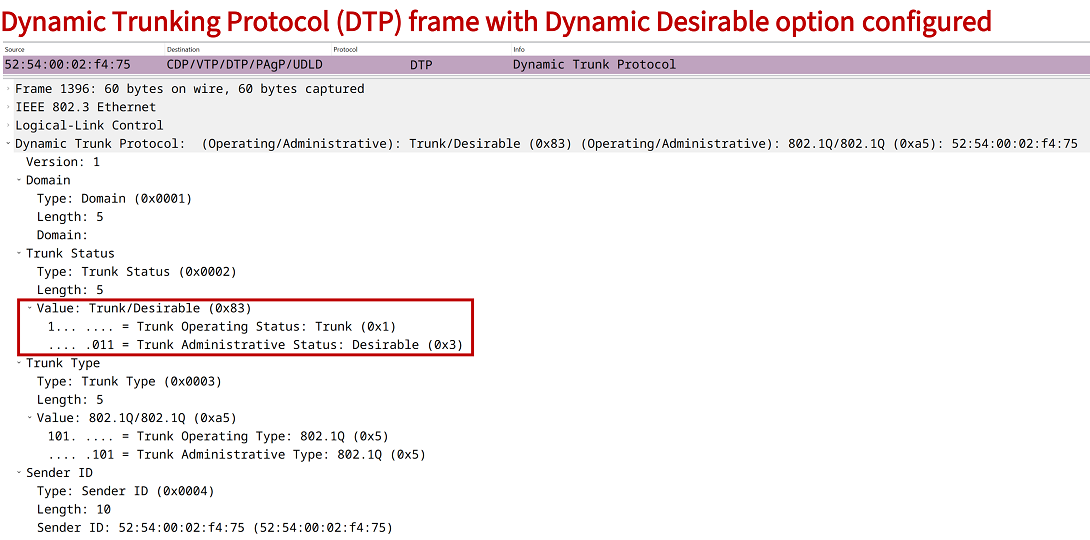
Static trunks are configured with the command switchport mode trunk. In this case the local switchport will be set to always trunk instead of negotiation. However, note that DTP frames are still being sent in an attempt to negotiate a trunk link on the other end. DTP frames are not transmitted on access ports.
DTP uses the native VLAN to transmit frames between two devices. This means, frames sent with DTP are always untagged, there is no VLAN tag added. The following packet capture shows an example DTP frame advertising the Dynamic Desirable setting.
VLAN double-tagged frame with Q-in-Q
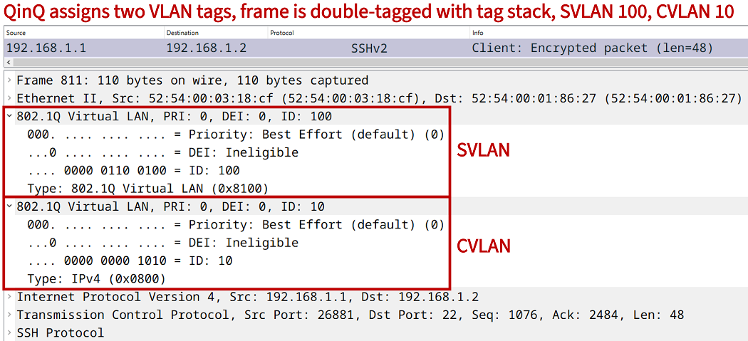
Multiple VLAN tags can be assigned to a single frame, this is called double-tagging. The resulting frame carries a tag stack that identifies two VLANs. This technology is enabled with Q-in-Q, and is commonly deployed in Service Provider networks to offer Layer-2 services.
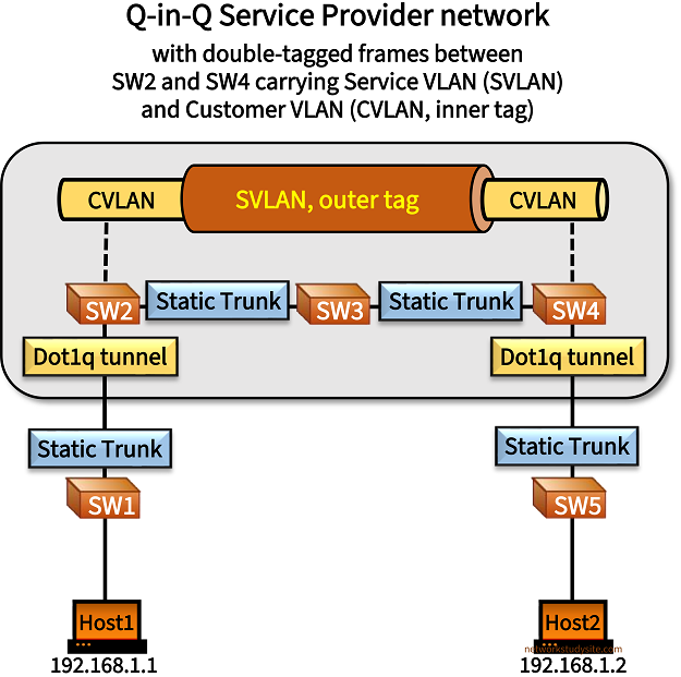
Two types of VLAN tags are differentiated with Q-in-Q. There is the Service VLAN (SVLAN) assigned by the Service Provider within its core network to identify traffic belonging to each customer. This tag is also called the outer tag. And there is the Customer VLAN (CVLAN) which is also called the inner tag. The CVLAN tag is added by the customer and the associated Layer-2 domain is stretched between different locations.
In the following topology Host1 and Host2 communicate with each other in VLAN 10. However, between SW2 and SW4 an additional VLAN tag is added, the SVLAN 100. Thus, frames between SW2 and SW4 have the inner tag (CVLAN) 10, and the outer tag (SVLAN) 100 assigned.
Configuration:
SW1
SW1#show run int Gi0/0 | sec int
interface GigabitEthernet0/0
 description ** to Host1 **
 switchport access vlan 10
 switchport mode access
 negotiation auto

SW1#show run int Gi0/1 | sec int
interface GigabitEthernet0/1
 description ** to SW2 **
 switchport trunk allowed vlan 10
 switchport trunk encapsulation dot1q
 switchport mode trunk
 negotiation auto
SW2
SW2#show run int Gi0/0 | sec int
interface GigabitEthernet0/0
 description ** to SW1 **
 switchport access vlan 100
 switchport mode dot1q-tunnel
 negotiation auto
 no cdp enable

SW2#show run int Gi0/1 | sec int
interface GigabitEthernet0/1
 description ** to SW3 **
 switchport trunk allowed vlan 100
 switchport trunk encapsulation dot1q
 switchport mode trunk
 negotiation auto
SW3
SW3#show run int Gi0/0 | sec int
interface GigabitEthernet0/0
 description ** to SW2 **
 switchport trunk allowed vlan 100
 switchport trunk encapsulation dot1q
 switchport mode trunk
 negotiation auto

SW3#show run int Gi0/1 | sec int
interface GigabitEthernet0/1
 description ** to SW4 **
 switchport trunk allowed vlan 100
 switchport trunk encapsulation dot1q
 switchport mode trunk
 negotiation auto
SW4
SW4#show run int Gi0/0 | sec int
interface GigabitEthernet0/0
 description ** to SW5 **
 switchport access vlan 100
 switchport mode dot1q-tunnel
 negotiation auto
 no cdp enable

SW4#show run int Gi0/1 | sec int
interface GigabitEthernet0/1
 description ** to SW3 **
 switchport trunk allowed vlan 100
 switchport trunk encapsulation dot1q
 switchport mode trunk
 negotiation auto
SW5
SW5#show run int Gi0/0 | sec int
interface GigabitEthernet0/0
 description ** to Host2 **
 switchport access vlan 10
 switchport mode access
 negotiation auto

SW5#show run int Gi0/1 | sec int
interface GigabitEthernet0/1
 description ** to SW4 **
 switchport trunk allowed vlan 10
 switchport trunk encapsulation dot1q
 switchport mode trunk
 negotiation auto
Host1
Host1#show run int Gi0/0 | sec int
interface GigabitEthernet0/0
 description ** to SW1 **
 ip address 192.168.1.1 255.255.255.0
 duplex auto
 speed auto
 media-type rj45
Host2
Host2#show run int Gi0/0 | sec int
interface GigabitEthernet0/0
 description ** to SW5 **
 ip address 192.168.1.2 255.255.255.0
 duplex auto
 speed auto
 media-type rj45
SW2#show dot1q

dot1q-tunnel mode LAN Port(s)
-----------------------------
Gi0/0                                   « SW2 interface Gi0/0 is a Q-in-Q tunnel endpoint


SW2#show int trunk

Port        Mode             Encapsulation  Status        Native vlan
Gi0/1       on               802.1q         trunking      1

Port        Vlans allowed on trunk
Gi0/1       100                          « SW2 has trunk link configured to SW3

Port        Vlans allowed and active in management domain
Gi0/1       100

Port        Vlans in spanning tree forwarding state and not pruned
Gi0/1       100


SW2#show vlan brief

VLAN Name                             Status    Ports
---- -------------------------------- --------- -------------------------------
1    default                          active    Gi0/2, Gi0/3
100  VLAN100                          active    Gi0/0            		         « SW2 only has VLAN 100 configured, and not VLAN 10
1002 fddi-default                     act/unsup
1003 token-ring-default               act/unsup
1004 fddinet-default                  act/unsup
1005 trnet-default                    act/unsup


Host1#ping 192.168.1.2
Type escape sequence to abort.
Sending 5, 100-byte ICMP Echos to 192.168.1.2, timeout is 2 seconds:
!!!!!
Success rate is 100 percent (5/5), round-trip min/avg/max = 7/7/7 ms                     « Host1 can reach Host2 through the Q-in-Q tunnel


Host1#show arp
Protocol  Address          Age (min)  Hardware Addr   Type   Interface
Internet  192.168.1.1             -   5254.0000.e9b8  ARPA   GigabitEthernet0/0
Internet  192.168.1.2           152   5254.0003.fcd9  ARPA   GigabitEthernet0/0          « Host1 has ARP cache entry for Host2


SW3#show mac address-table
          Mac Address Table
-------------------------------------------

Vlan    Mac Address       Type        Ports
----    -----------       --------    -----
 100    5254.0000.e9b8    DYNAMIC     Gi0/0               « SW3 forwards traffic in SVLAN 100 but learns about the MAC addresses in the CVLAN
 100    5254.0003.fcd9    DYNAMIC     Gi0/1
 100    5254.001c.fd59    DYNAMIC     Gi0/1
Total Mac Addresses for this criterion: 3
The following packet capture shows a double-tagged frame which is forwarded between SW2 and SW4 in the Q-in-Q tunnel. The frame carries IP traffic initiated by Host1 and destined to Host2. As visible, the outer VLAN tag is at the top, and the inner VLAN tag is at the bottom.