Policy-Based Routing Detailed Guide with Configurations
Table of Contents
Jump to section:
- • What is Policy-Based Routing (PBR)?
- • How to configure Policy-Based Routing?
- • PBR configuration with multi-homed network
- • PBR configuration with the "set ip default next-hop" command
- • PBR next-hop address availability tracking with IP SLA
- • PBR configuration route-map deny statement
- • PBR configuration with MPLS Traffic Engineering tunnel
- • Download section
- What is Policy-Based Routing (PBR)? ‹
- How to configure Policy-Based Routing? ‹
- PBR configuration with multi-homed network ‹
- PBR configuration with the "set ip default next-hop" command ‹
- PBR next-hop address availability tracking with IP SLA ‹
- PBR configuration route-map deny statement ‹
- PBR configuration with MPLS Traffic Engineering tunnel ‹
- Download section ‹
What is Policy-Based Routing (PBR)?
Policy-based routing uses a route-map to statically determine the forwarding path of network traffic. PBR is configured inbound on an interface, and is a method to enforce specific rules of path control that statically define a next-hop address for transiting traffic. The following list includes three scenarios where PBR is used.
- two links are available to a destination and voice traffic should prefer the link where QoS (Quality of Service) can be guaranteed
- based on the source of the traffic some flows need to go through a firewall or deep packet inspection
- an MPLS Traffic Engineering (MPLS TE) tunnel is configured and traffic should be sent across the tunnel
How to configure Policy-Based Routing?
There are three main elements that need to be configured. First, an access-list (ACL) defines the particular characteristics to select traffic, such as a source IP address or QoS value. In the following example IP packets from the source subnet 192.168.1.0/24 with the QoS value for voice traffic will be considered for PBR.
R1>
R1>enable
R1#configure terminal
Enter configuration commands, one per line.  End with CNTL/Z.
R1(config)#ip access-list extended ACL-PBR
R1(config-ext-nacl)#permit ip 192.168.1.0 0.0.0.255 any dscp ef
R1(config-ext-nacl)#exit
R1(config)#
In the second step, the ACL is applied to a route-map which decides what action to take with the traffic. The route-map defines the specific policy, such as a next-hop IP address. Currently, traffic from 192.168.1.0/24 in the voice class will choose 10.2.0.2 as its next-hop IP address.
R1(config)#
R1(config)#route-map RMAP-PBR permit 10
R1(config-route-map)#match ip address ACL-PBR
R1(config-route-map)#set ip next-hop 10.2.0.2
R1(config-route-map)#exit
R1(config)#
Finally, the route-map is applied to an incoming interface. In other words, traffic that is subject to policy routing will arrive on R1 interface Gi0/0, and will exit on whichever interface is defined by PBR on R1. The configuration is shown in the following output.
R1(config)#
R1(config)#interface GigabitEthernet 0/0
R1(config-if)#ip policy route-map RMAP-PBR
R1(config-if)#exit
R1(config)#
PBR configuration with multi-homed network
In the following example topology R1 receives two default routes through DHCP, one from R2 and another from R3. The default route received from R2 is used as the primary gateway address. However, policy-based routing (PBR) on R1 is configured to specifically send voice traffic towards R3.
This is achieved using an extended access-list (ACL) on R1, which selects traffic in the DHCP class for Expedited Forwarding (TOS value 184). This class is commonly used to forward real-time voice traffic. If the ACL matches such traffic, then the configured route-map assigns the next-hop IP address of R3 (10.2.0.2). Thus, instead of using the primary default route towards R2, voice traffic goes towards R3.

Configuration:
R1
R1#show run int Gi0/0 | sec int
interface GigabitEthernet0/0
 description ** to Site 1 **
 ip address 192.168.1.3 255.255.255.0
 ip policy route-map RMAP-PBR
 duplex auto
 speed auto
 media-type rj45

R1#show run int Gi0/1 | sec int
interface GigabitEthernet0/1
 description ** to R2 - AS65001 **
 ip address dhcp
 duplex auto
 speed auto
 media-type rj45

R1#show run int Gi0/2 | sec int
interface GigabitEthernet0/2
 description ** to R3 - AS65002 **
 ip address dhcp
 duplex auto
 speed auto
 media-type rj45

R1#show run | sec ^route-map
route-map RMAP-PBR permit 10
 match ip address ACL-PBR
 set ip next-hop 10.2.0.2

R1#show run | sec ^ip access
ip access-list extended ACL-PBR
 permit ip 192.168.1.0 0.0.0.255 any dscp ef

R1#show run | sec ^ip route
ip route 0.0.0.0 0.0.0.0 GigabitEthernet0/1 dhcp 5
ip route 0.0.0.0 0.0.0.0 GigabitEthernet0/2 dhcp 10
R2
R2#show run int Gi0/0 | sec int
interface GigabitEthernet0/0
 description ** to R1 - Site 1 **
 ip address 10.1.0.2 255.255.255.252
 duplex auto
 speed auto
 media-type rj45

R2#show run int Gi0/1 | sec int
interface GigabitEthernet0/1
 description ** to R4 - Site 2 **
 ip address 10.3.0.2 255.255.255.252
 duplex auto
 speed auto
 media-type rj45

R2#show run | sec ^ip dhcp
ip dhcp pool DHCP-SITE1
 network 10.1.0.0 255.255.255.252
 default-router 10.1.0.2

R2#show run | sec ^router
router bgp 65001
 bgp router-id 2.2.2.2
 bgp log-neighbor-changes
 network 192.168.1.0
 neighbor 10.3.0.1 remote-as 65100

R2#show run | sec ^ip route
ip route 192.168.1.0 255.255.255.0 GigabitEthernet0/0 10.1.0.1
R3
R3#show run int Gi0/0 | sec int
interface GigabitEthernet0/0
 description ** to R1 - Site 1 **
 ip address 10.2.0.2 255.255.255.252
 duplex auto
 speed auto
 media-type rj45

R3#show run int Gi0/1 | sec int
interface GigabitEthernet0/1
 description ** to R4 - Site 2 **
 ip address 10.4.0.2 255.255.255.252
 duplex auto
 speed auto
 media-type rj45

R3#show run | sec ^ip dhcp
ip dhcp pool DHCP-SITE1
 network 10.2.0.0 255.255.255.252
 default-router 10.2.0.2

R3#show run | sec ^router
router bgp 65002
 bgp router-id 3.3.3.3
 bgp log-neighbor-changes
 network 192.168.1.0
 neighbor 10.4.0.1 remote-as 65100

R3#show run | sec ^ip route
ip route 192.168.1.0 255.255.255.0 GigabitEthernet0/0 10.2.0.1
R4
R4#show run int Gi0/0 | sec int
interface GigabitEthernet0/0
 description ** to R2 - AS 65001 **
 ip address 10.3.0.1 255.255.255.252
 duplex auto
 speed auto
 media-type rj45

R4#show run int Gi0/1 | sec int
interface GigabitEthernet0/1
 description ** to R3 - AS 65002 **
 ip address 10.4.0.1 255.255.255.252
 duplex auto
 speed auto
 media-type rj45

R4#show run | sec ^router
router bgp 65100
 bgp router-id 4.4.4.4
 bgp log-neighbor-changes
 network 192.168.2.0
 neighbor 10.3.0.2 remote-as 65001
 neighbor 10.3.0.2 route-map RMAP-LOCPREF in
 neighbor 10.4.0.2 remote-as 65002

R4#show run | sec ^route-map
route-map RMAP-LOCPREF permit 10
 set local-preference 150
R1#show ip route static | begin Ga
Gateway of last resort is 10.1.0.2 to network 0.0.0.0

S*    0.0.0.0/0 [5/0] via 10.1.0.2, GigabitEthernet0/1      « The installed default route points to R2


Host1:~$ traceroute 192.168.2.1 -q 1 -n -t 0                « QoS default class (TOS 0) uses R2
traceroute to 192.168.2.1 (192.168.2.1), 30 hops max, 46 byte packets
 1  192.168.1.3  0.939 ms
 2  10.1.0.2  22.564 ms
 3  10.3.0.1  22.856 ms
 4  192.168.2.1  23.285 ms


Host1:~$ traceroute 192.168.2.1 -q 1 -n -t 136              « QoS multimedia class (TOS 136) uses R2
traceroute to 192.168.2.1 (192.168.2.1), 30 hops max, 46 byte packets
 1  192.168.1.3  0.935 ms
 2  10.1.0.2  21.944 ms
 3  10.3.0.1  22.468 ms
 4  192.168.2.1  23.272 ms


Host1:~$ traceroute 192.168.2.1 -q 1 -n -t 184              « However, QoS voice class (TOS 184) uses R3
traceroute to 192.168.2.1 (192.168.2.1), 30 hops max, 46 byte packets
 1  192.168.1.3  0.884 ms
 2  10.2.0.2  22.728 ms
 3  10.4.0.1  23.800 ms
 4  192.168.2.1  23.080 ms


R1#show ip policy
Interface      Route map
Gi0/0          RMAP-PBR         « Policy-based routing is configured on R1 interface Gi0/0


R1#show ip access-list ACL-PBR
Extended IP access list ACL-PBR
    10 permit ip 192.168.1.0 0.0.0.255 any dscp ef (21 matches)     « The ACL has matched voice traffic
PBR configuration with the "set ip default next-hop" command
This example scenario uses policy-routing as a failover mechanism to steer traffic through a backup GRE tunnel. The details and configuration are explained below.
- Site 1 is connected with two providers (R2 and R3). R2 is the primary connection advertising the Site 2 prefix 192.168.2.0/24 via eBGP to R1, simulating an MPLS L3VPN network. However, R1 also has a tunnel configured with R4 over a backup lower quality internet connection. A dynamic routing protocol is not configured over the tunnel.
- R3 uses DHCP to provide an IP address and a default route for R1. R1 uses the DHCP IP address however does not allow installation of the DHCP default route. The interface-level command no ip dhcp client request router accomplishes this on R1. Instead of a default route, R1 uses a static host route to reach R4 through R3.
- For the failover to happen, R1 uses policy-based routing with the command set ip default next-hop 172.16.0.2 to reach the tunnel endpoint on R4. This means, until the Site 2 prefix is installed via BGP on R1, policy-routing does not take effect. Or in other words, the default keyword ensures a matching destination prefix is first verified in the routing table, before choosing policy-routing.

Configuration:
R1
R1#show run int Gi0/0 | sec int
interface GigabitEthernet0/0
 description ** to Site 1 **
 ip address 192.168.1.3 255.255.255.0
 ip policy route-map RMAP-PBR
 duplex auto
 speed auto
 media-type rj45

R1#show run | sec ^route-map
route-map RMAP-PBR permit 10
 match ip address ACL-PBR
 set ip default next-hop 172.16.0.2

R1#show run | sec ^ip access
ip access-list extended ACL-PBR
 permit ip host 192.168.1.1 any

R1#show run int Gi0/1 | sec int
interface GigabitEthernet0/1
 description ** to R2 - AS65001 **
 ip address 10.1.0.1 255.255.255.252
 duplex auto
 speed auto
 media-type rj45
 bfd interval 100 min_rx 50 multiplier 3

R1#show run int Gi0/2 | sec int
interface GigabitEthernet0/2
 description ** to R3 - AS65002 **
 no ip dhcp client request router
 ip address dhcp
 duplex auto
 speed auto
 media-type rj45

R1#show run int Tu10 | sec int
interface Tunnel10
 description ** Tunnel to Site 2 **
 ip address 172.16.0.1 255.255.255.252
 tunnel source GigabitEthernet0/2
 tunnel destination 10.4.0.1

R1#show run | sec ^ip route
ip route 10.4.0.1 255.255.255.255 GigabitEthernet0/2 10.2.0.2
R2
R2#show run int Gi0/0 | sec int
interface GigabitEthernet0/0
 description ** to R1 - Site 1 **
 ip address 10.1.0.2 255.255.255.252
 duplex auto
 speed auto
 media-type rj45
 bfd interval 100 min_rx 50 multiplier 3

R2#show run int Gi0/1 | sec int
interface GigabitEthernet0/1
 description ** to R4 - Site 2 **
 ip address 10.3.0.2 255.255.255.252
 duplex auto
 speed auto
 media-type rj45
 bfd interval 100 min_rx 50 multiplier 3

R2#show run | sec ^router
router bgp 65001
 bgp router-id 2.2.2.2
 bgp log-neighbor-changes
 neighbor 10.1.0.1 remote-as 65100
 neighbor 10.1.0.1 fall-over bfd
 neighbor 10.3.0.1 remote-as 65200
 neighbor 10.3.0.1 fall-over bfd
R3
R3#show run int Gi0/0 | sec int
interface GigabitEthernet0/0
 description ** to R1 - Site 1 **
 ip address 10.2.0.2 255.255.255.252
 duplex auto
 speed auto
 media-type rj45

R3#show run int Gi0/1 | sec int
interface GigabitEthernet0/1
 description ** to R4 - Site 2 **
 ip address 10.4.0.2 255.255.255.252
 duplex auto
 speed auto
 media-type rj45

R3#show run | sec ^router
router bgp 65002
 bgp router-id 3.3.3.3
 bgp log-neighbor-changes
 network 10.2.0.0 mask 255.255.255.252
 neighbor 10.4.0.1 remote-as 65200

R3#show run | sec ^ip dhcp
ip dhcp pool DHCP-SITE1
 network 10.2.0.0 255.255.255.252
 default-router 10.2.0.2
R4
R4#show run int Gi0/0 | sec int
interface GigabitEthernet0/0
 description ** to Site 2 **
 ip address 192.168.2.2 255.255.255.0
 duplex auto
 speed auto
 media-type rj45

R4#show run int Gi0/1 | sec int
interface GigabitEthernet0/1
 description ** to R2 - AS65001 **
 ip address 10.3.0.1 255.255.255.252
 duplex auto
 speed auto
 media-type rj45
 bfd interval 100 min_rx 50 multiplier 3

R4#show run int Gi0/2 | sec int
interface GigabitEthernet0/2
 description ** to R3 - AS65002 **
 ip address 10.4.0.1 255.255.255.252
 duplex auto
 speed auto
 media-type rj45

R4#show run int Tu10 | sec int
interface Tunnel10
 description ** Tunnel to Site 1 **
 ip address 172.16.0.2 255.255.255.252
 tunnel source GigabitEthernet0/2
 tunnel destination 10.2.0.1

R4#show run | sec ^router
router bgp 65200
 bgp router-id 4.4.4.4
 bgp log-neighbor-changes
 network 192.168.2.0
 neighbor 10.3.0.2 remote-as 65001
 neighbor 10.3.0.2 fall-over bfd
 neighbor 10.4.0.2 remote-as 65002

R4#show run | sec ^ip route
ip route 192.168.1.0 255.255.255.0 Tunnel10 172.16.1.1 21
R1#show ip route | beg Ga
Gateway of last resort is not set

      10.0.0.0/8 is variably subnetted, 5 subnets, 2 masks
C        10.1.0.0/30 is directly connected, GigabitEthernet0/1
L        10.1.0.1/32 is directly connected, GigabitEthernet0/1
C        10.2.0.0/30 is directly connected, GigabitEthernet0/2
L        10.2.0.1/32 is directly connected, GigabitEthernet0/2
S        10.4.0.1/32 [1/0] via 10.2.0.2, GigabitEthernet0/2
      172.16.0.0/16 is variably subnetted, 2 subnets, 2 masks
C        172.16.0.0/30 is directly connected, Tunnel10
L        172.16.0.1/32 is directly connected, Tunnel10
      192.168.1.0/24 is variably subnetted, 2 subnets, 2 masks
C        192.168.1.0/24 is directly connected, GigabitEthernet0/0
L        192.168.1.3/32 is directly connected, GigabitEthernet0/0
B     192.168.2.0/24 [20/0] via 10.1.0.2, 00:46:47                                    « eBGP advertises Site 2 prefix


R1#show ip policy
Interface      Route map
Gi0/0          RMAP-PBR


R1#show ip int br
Interface                  IP-Address      OK? Method Status                Protocol
GigabitEthernet0/0         192.168.1.3     YES manual up                    up
GigabitEthernet0/1         10.1.0.1        YES manual up                    up
GigabitEthernet0/2         10.2.0.1        YES DHCP   up                    up        « Address learned with DHCP
GigabitEthernet0/3         unassigned      YES unset  administratively down down
Tunnel10                   172.16.0.1      YES manual up                    up        « GRE tunnel to Site 2 is up
So in effect, policy-routing on R1 first looks at the routing table (RIB) to verify the destination IP address of incoming packets. If the IP address is in the routing table, then normal packet forwarding happens based on the RIB. However, if the destination address is not in R1's RIB, then traffic goes via policy-routing through the GRE tunnel.
The above routing table output shows there is no DHCP default route installed, and the Site 2 prefix 192.168.2.0/24 is received via eBGP. Also, the interface output shows that the tunnel connection between R1 and R4 is established.
The following outputs show the failover happening. Notice how there is lower latency before the failover, and a higher latency after traffic failover to the backup tunnel. Also, the PBR configuration enables to specifically select which source address is permitted to use the backup tunnel.
Host1#trace 192.168.2.1 probe 1
Type escape sequence to abort.
Tracing the route to 192.168.2.1
VRF info: (vrf in name/id, vrf out name/id)
  1 192.168.1.3 3 msec
  2 10.1.0.2 2 msec                       « Host1 uses the primary connection to reach the Server
  3 10.3.0.1 25 msec
  4 192.168.2.1 24 msec


Host1#ping 192.168.2.1 re 10
Type escape sequence to abort.
Sending 10, 100-byte ICMP Echos to 192.168.2.1, timeout is 2 seconds:
!!!!!!!!!!
Success rate is 100 percent (10/10), round-trip min/avg/max = 24/25/27 ms        « Average RTT is 25 ms


Host1#ping 192.168.2.1 re 100
Type escape sequence to abort.
Sending 100, 100-byte ICMP Echos to 192.168.2.1, timeout is 2 seconds:
!!!!!!!!!!!!!!!!!!!!!!!!!!!!!!.!!!!!!!!!!!!!!!!!!!!!!!!!!!!!!!!!!!!!!!           « This is when the failover happens to the backup tunnel
!!!!!!!!!!!!!!!!!!!!!!!!!!!!!!
Success rate is 99 percent (99/100), round-trip min/avg/max = 23/108/148 ms


Host1#ping 192.168.2.1 re 10
Type escape sequence to abort.
Sending 10, 100-byte ICMP Echos to 192.168.2.1, timeout is 2 seconds:
!!!!!!!!!!
Success rate is 100 percent (10/10), round-trip min/avg/max = 144/145/153 ms     « Average RTT is now 145


Host1#trace 192.168.2.1 probe 1
Type escape sequence to abort.
Tracing the route to 192.168.2.1
VRF info: (vrf in name/id, vrf out name/id)
  1 192.168.1.3 1 msec
  2 172.16.0.2 145 msec                   « Host1 now uses the backup tunnel to reach the Server
  3 192.168.2.1 146 msec


Host2#ping 192.168.2.1
Type escape sequence to abort.
Sending 5, 100-byte ICMP Echos to 192.168.2.1, timeout is 2 seconds:
U.U.U
Success rate is 0 percent (0/5)           « As per the PBR configuration on R1, Host2 cannot access the backup tunnel
The command debug ip policy is issued to verify policy routing on R1 before and after the failover to the backup tunnel. It is visible that while the eBGP route is received from R2, policy-routing is rejected (ignored).
R1#show log | beg Log Buffer
Log Buffer (8192 bytes):

IP: s=192.168.1.1 (GigabitEthernet0/0), d=192.168.2.1, len 100, FIB policy match
IP: s=192.168.1.1 (GigabitEthernet0/0), d=192.168.2.1, len 100, PBR Counted
IP: s=192.168.1.1 (GigabitEthernet0/0), d=192.168.2.1, len 100, FIB policy rejected(explicit route) - normal forwarding
IP: s=192.168.1.1 (GigabitEthernet0/0), d=192.168.2.1, len 100, FIB policy match
IP: s=192.168.1.1 (GigabitEthernet0/0), d=192.168.2.1, len 100, PBR Counted
IP: s=192.168.1.1 (GigabitEthernet0/0), d=192.168.2.1, len 100, FIB policy rejected(explicit route) - normal forwarding
IP: s=192.168.1.1 (GigabitEthernet0/0), d=192.168.2.1, len 100, FIB policy match
IP: s=192.168.1.1 (GigabitEthernet0/0), d=192.168.2.1, len 100, PBR Counted
IP: s=192.168.1.1 (GigabitEthernet0/0), d=192.168.2.1, len 100, FIB policy rejected(explicit route) - normal forwarding


R1#show log | beg Log Buffer
Log Buffer (8192 bytes):

IP: s=192.168.1.1 (GigabitEthernet0/0), d=192.168.2.1, len 100, FIB policy match
IP: s=192.168.1.1 (GigabitEthernet0/0), d=192.168.2.1, len 100, PBR Counted
IP: s=192.168.1.1 (GigabitEthernet0/0), d=192.168.2.1, g=172.16.0.2, len 100, FIB policy routed
IP: s=192.168.1.1 (GigabitEthernet0/0), d=192.168.2.1, len 100, FIB policy match
IP: s=192.168.1.1 (GigabitEthernet0/0), d=192.168.2.1, len 100, PBR Counted
IP: s=192.168.1.1 (GigabitEthernet0/0), d=192.168.2.1, g=172.16.0.2, len 100, FIB policy routed
IP: s=192.168.1.1 (GigabitEthernet0/0), d=192.168.2.1, len 100, FIB policy match
IP: s=192.168.1.1 (GigabitEthernet0/0), d=192.168.2.1, len 100, PBR Counted
IP: s=192.168.1.1 (GigabitEthernet0/0), d=192.168.2.1, g=172.16.0.2, len 100, FIB policy routed
PBR next-hop address availability tracking with IP SLA
In the following example scnenario R1 has dual connections to the internet through R2 and R3. The primary connection is R1 - R2. Policy-routing is configured to steer traffic on the primary path if R2 is reachable. The reachability of R2 is verified with an ICMP-Echo IP SLA and object tracking configured on R1. The following PBR route-map configuration is applied on R1.
R1>
R1>enable
R1#configure terminal
Enter configuration commands, one per line.  End with CNTL/Z.
R1(config)#route-map RMAP-PBR permit 10
R1(config-route-map)#match ip address prefix-list PL-PBR
R1(config-route-map)#set ip next-hop verify-availability 10.1.0.2 1 track 15
R1(config-route-map)#set ip next-hop 10.2.0.2
R1(config-route-map)#
R1(config-route-map)#exit
R1(config)#
R1(config)#interface Gi0/0
R1(config-if)#ip policy route-map RMAP-PBR
R1(config-if)#
R1(config-if)#exit
R1(config)#exit
R1#
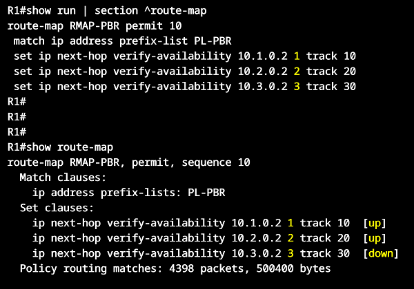
The command set ip next-hop verify-availability 10.1.0.2 1 track 15 means that policy-routing steers traffic towards 10.1.0.2 if track object 15 is up. The number 1 (visible right after the IP address) is the sequence number that is assigned to this next-hop entry. If needed, there can be multiple next-hop entries added to a PBR route-map in sequential order.

Configuration:
R1
R1#show run int Gi0/0 | sec int
interface GigabitEthernet0/0
 description ** to Site 1 **
 ip address 192.168.1.3 255.255.255.0
 ip policy route-map RMAP-PBR
 duplex auto
 speed auto
 media-type rj45

R1#show run int Gi0/1 | sec int
interface GigabitEthernet0/1
 description ** to R2 **
 no ip dhcp client request router
 ip address dhcp
 duplex auto
 speed auto
 media-type rj45

R1#show run int Gi0/2 | sec int
interface GigabitEthernet0/2
 description ** to R3 **
 no ip dhcp client request router
 ip address dhcp
 duplex auto
 speed auto
 media-type rj45

R1#show run | sec ^route-map
route-map RMAP-PBR permit 10
 match ip address prefix-list PL-PBR
 set ip next-hop verify-availability 10.1.0.2 1 track 15
 set ip next-hop 10.2.0.2

R1#show run | sec ^ip prefix
ip prefix-list PL-PBR seq 5 permit 192.168.1.0/24

R1#show run | sec ^track
track 15 ip sla 10

R1#show run | sec ^ip sla
ip sla 10
 icmp-echo 10.1.0.2 source-interface GigabitEthernet0/1
 threshold 1000
 timeout 1000
 frequency 1
ip sla schedule 10 life forever start-time now
R1#show route-map
route-map RMAP-PBR, permit, sequence 10
  Match clauses:
    ip address prefix-lists: PL-PBR
  Set clauses:
    ip next-hop verify-availability 10.1.0.2 1 track 15  [up]        « Next-hop to 10.1.0.2 is active
    ip next-hop 10.2.0.2
  Policy routing matches: 4398 packets, 500400 bytes


R1#show track brief
Track Type        Instance                   Parameter        State Last Change
15    ip sla      10                         state            Up    00:08:37        « Track object 15 is Up


Host1#trace 192.168.2.1 probe 1
Type escape sequence to abort.
Tracing the route to 192.168.2.1
VRF info: (vrf in name/id, vrf out name/id)
  1 192.168.1.3 2 msec
  2 10.1.0.2 24 msec                   « PBR sends traffic on primary link
  3 10.3.0.1 25 msec
  4 192.168.2.1 24 msec


Host1#trace 192.168.2.1 probe 1
Type escape sequence to abort.
Tracing the route to 192.168.2.1
VRF info: (vrf in name/id, vrf out name/id)
  1 192.168.1.3 2 msec
  2 10.2.0.2 2 msec                    « After primary link failure, PBR sends traffic on backup path
  3 10.4.0.1 144 msec
  4 192.168.2.1 146 msec


R1#show route-map
route-map RMAP-PBR, permit, sequence 10
  Match clauses:
    ip address prefix-lists: PL-PBR
  Set clauses:
    ip next-hop verify-availability 10.1.0.2 1 track 15  [down]         « Next-hop to 10.1.0.2 is no longer active
    ip next-hop 10.2.0.2                                                « Next-hop to backup path 10.2.0.2 is active
  Policy routing matches: 4504 packets, 512160 bytes


R1#show ip route | beg Ga
Gateway of last resort is not set

      10.0.0.0/8 is variably subnetted, 4 subnets, 2 masks
C        10.1.0.0/30 is directly connected, GigabitEthernet0/1
L        10.1.0.1/32 is directly connected, GigabitEthernet0/1
C        10.2.0.0/30 is directly connected, GigabitEthernet0/2
L        10.2.0.1/32 is directly connected, GigabitEthernet0/2
      192.168.1.0/24 is variably subnetted, 2 subnets, 2 masks
C        192.168.1.0/24 is directly connected, GigabitEthernet0/0
L        192.168.1.3/32 is directly connected, GigabitEthernet0/0
As visible in the above routing table output from R1, there is no default route installed even though the interfaces receive IP address via DHCP. This is accomplished with the interface-level command no ip dhcp client request router which instructs R1 not to accept DHCP default-routes through a particular interface.
PBR configuration route-map deny statement
Given the same scenario as in the previous section (ip next-hop verify-availability) now the following configuration is applied. Notice the only difference is that the route-map has a deny statement instead of a permit statement.
R1>
R1>enable
R1#configure terminal
Enter configuration commands, one per line.  End with CNTL/Z.
R1(config)#route-map RMAP-PBR deny 10
R1(config-route-map)#match ip address prefix-list PL-PBR
R1(config-route-map)#set ip next-hop verify-availability 10.1.0.2 1 track 15
R1(config-route-map)#set ip next-hop 10.2.0.2
R1(config-route-map)#
R1(config-route-map)#exit
R1(config)#
R1(config)#interface Gi0/0
R1(config-if)#ip policy route-map RMAP-PBR
R1(config-if)#
R1(config-if)#exit
R1(config)#exit
R1#
R1#
R1#show route-map
route-map RMAP-PBR, deny, sequence 10
  Match clauses:
    ip address prefix-lists: PL-PBR
  Set clauses:
    ip next-hop verify-availability 10.1.0.2 1 track 15  [up]
    ip next-hop 10.2.0.2
  Policy routing matches: 0 packets, 0 bytes
R1#
R1#
R1#show ip route | beg Ga
Gateway of last resort is not set

      10.0.0.0/8 is variably subnetted, 4 subnets, 2 masks
C        10.1.0.0/30 is directly connected, GigabitEthernet0/1
L        10.1.0.1/32 is directly connected, GigabitEthernet0/1
C        10.2.0.0/30 is directly connected, GigabitEthernet0/2
L        10.2.0.1/32 is directly connected, GigabitEthernet0/2
      192.168.1.0/24 is variably subnetted, 2 subnets, 2 masks
C        192.168.1.0/24 is directly connected, GigabitEthernet0/0
L        192.168.1.3/32 is directly connected, GigabitEthernet0/0

------------------------------------------------------------------

Host1#ping 192.168.2.1
Type escape sequence to abort.
Sending 5, 100-byte ICMP Echos to 192.168.2.1, timeout is 2 seconds:
U.U.U
Success rate is 0 percent (0/5)
As a result of this configuration, hosts in Site 1 cannot reach the Server on the internet. This is because the PBR route-map with a deny statement instructs R1 to bypass policy-routing for the matched prefix-list addresses. So even though the policy-routing next-hop availability is confirmed, the traffic originating in Site 1 does not use PBR and instead is normally forwarded based on R1's RIB.
However, since R1 does not install DHCP default-routes (R1 RIB shown in the above outputs) there is no matching route and no valid next-hop address for traffic egressing (leaving) Site 1, and consequently traffic from Host1 is dropped.
PBR configuration with MPLS Traffic Engineering tunnel
In the following example topology two Customer Edge (CE) routers are connected through an MPLS network. The Provider Edge (PE) routers use MPLS Traffic Engineering (MPLS TE) tunnels two create a label switched path (LSP). Policy-based routing (PBR) is configured on the PE routers to ensure that traffic originating from the CE routers chooses the MPLS TE tunnel.
Note that a dynamic routing protocol cannot be configured across an MPLS TE tunnel, and this is why other methods - such as PBR - are used to send traffic through the tunnel. The PBR configuration is applied on the CE-facing interface of the PE router.

Configuration:
R2 (PE)
R2#show run | sec ^mpls
mpls label range 200 299
mpls traffic-eng tunnels

R2#show run int Lo10 | sec int
interface Loopback10
 ip address 2.2.2.2 255.255.255.255

R2#show run int Gi1 | sec int
interface GigabitEthernet1
 description ** to CE router R1 **
 ip address 10.0.1.2 255.255.255.252
 ip policy route-map RMAP-PBR
 negotiation auto
 no mop enabled
 no mop sysid

R2#show run int Gi2 | sec int
interface GigabitEthernet2
 description ** to R3 **
 ip address 10.1.0.1 255.255.255.252
 ip ospf network point-to-point
 negotiation auto
 mpls traffic-eng tunnels
 no mop enabled
 no mop sysid
 ip rsvp bandwidth 10 10

R2#show run int Tu10 | sec int
interface Tunnel10
 description ** MPLS TE tunnel to PE R6 **
 ip unnumbered Loopback10
 tunnel mode mpls traffic-eng
 tunnel destination 6.6.6.6
 tunnel mpls traffic-eng priority 1 1
 tunnel mpls traffic-eng bandwidth 10
 tunnel mpls traffic-eng path-option 1 dynamic

R2#show run | sec ^route-map
route-map RMAP-PBR permit 10
 match ip address ACL-PBR
 set interface Tunnel10

R2#show run | sec ^ip access
ip access-list extended ACL-PBR
 10 permit ip 10.0.1.0 0.0.0.3 10.0.2.0 0.0.0.3

R2#show run | sec ^router ospf
router ospf 10
 router-id 2.2.2.2
 passive-interface GigabitEthernet1
 network 2.2.2.2 0.0.0.0 area 0
 network 10.0.1.0 0.0.0.3 area 0
 network 10.1.0.0 0.0.0.3 area 0
 mpls traffic-eng router-id Loopback10
 mpls traffic-eng area 0
R6 (PE)
R6#show run | sec ^mpls
mpls label range 600 699
mpls traffic-eng tunnels

R6#show run int Lo10 | sec int
interface Loopback10
 ip address 6.6.6.6 255.255.255.255

R6#show run int Gi1 | sec int
interface GigabitEthernet1
 description ** to CE router R7 **
 ip address 10.0.2.2 255.255.255.252
 ip policy route-map RMAP-PBR
 negotiation auto
 no mop enabled
 no mop sysid

R6#show run int Gi2 | sec int
interface GigabitEthernet2
 description ** to R5 **
 ip address 10.4.0.1 255.255.255.252
 ip ospf network point-to-point
 negotiation auto
 mpls traffic-eng tunnels
 no mop enabled
 no mop sysid
 ip rsvp bandwidth 10 10

R6#show run int Tu10 | sec int
interface Tunnel10
 description ** MPLS TE tunnel to PE R2 **
 ip unnumbered Loopback10
 tunnel mode mpls traffic-eng
 tunnel destination 2.2.2.2
 tunnel mpls traffic-eng priority 1 1
 tunnel mpls traffic-eng bandwidth 10
 tunnel mpls traffic-eng path-option 1 dynamic

R6#show run | sec ^route-map
route-map RMAP-PBR permit 10
 match ip address ACL-PBR
 set interface Tunnel10

R6#show run | sec ^ip access-list
ip access-list extended ACL-PBR
 10 permit ip 10.0.2.0 0.0.0.3 10.0.1.0 0.0.0.3

R6#show run | sec ^router ospf
router ospf 10
 router-id 6.6.6.6
 passive-interface GigabitEthernet1
 network 6.6.6.6 0.0.0.0 area 0
 network 10.0.2.0 0.0.0.3 area 0
 network 10.4.0.0 0.0.0.3 area 0
 mpls traffic-eng router-id Loopback10
 mpls traffic-eng area 0
R1 (CE)
R1#show run int Gi0/0 | sec int
interface GigabitEthernet0/0
 description ** to PE R2 **
 ip address 10.0.1.1 255.255.255.0
 duplex auto
 speed auto
 media-type rj45

R1#show run | sec ^ip route
ip route 0.0.0.0 0.0.0.0 GigabitEthernet0/0 10.0.1.2
R7 (CE)
R7#show run int Gi0/0 | sec int
interface GigabitEthernet0/0
 description ** to PE R6 **
 ip address 10.0.2.1 255.255.255.0
 duplex auto
 speed auto
 media-type rj45

R7#show run | sec ^ip route
ip route 0.0.0.0 0.0.0.0 GigabitEthernet0/0 10.0.2.2
R3 (P router)
R3#show run | sec ^mpls
mpls label range 300 399
mpls traffic-eng tunnels

R3#show run int Lo10 | sec int
interface Loopback10
 ip address 3.3.3.3 255.255.255.255

R3#show run int Gi0/0 | sec int
interface GigabitEthernet0/0
 description ** to PE router R2 **
 ip address 10.1.0.2 255.255.255.252
 ip ospf network point-to-point
 duplex auto
 speed auto
 media-type rj45
 mpls traffic-eng tunnels
 ip rsvp bandwidth 10 10

R3#show run int Gi0/1 | sec int
interface GigabitEthernet0/1
 description ** to R4 **
 ip address 10.2.0.1 255.255.255.252
 ip ospf network point-to-point
 duplex auto
 speed auto
 media-type rj45
 mpls traffic-eng tunnels
 ip rsvp bandwidth 10 10

R3#show run | sec ^router
router ospf 10
 mpls traffic-eng router-id Loopback10
 mpls traffic-eng area 0
 router-id 3.3.3.3
 network 3.3.3.3 0.0.0.0 area 0
 network 10.1.0.0 0.0.0.3 area 0
 network 10.2.0.0 0.0.0.3 area 0
R2#show mpls traffic-eng tunnels brief
Signalling Summary:
    LSP Tunnels Process:            running
    Passive LSP Listener:           running
    RSVP Process:                   running
    Forwarding:                     enabled
    auto-tunnel:
        p2p    Disabled (0), id-range:62336-64335

    Periodic reoptimization:        every 3600 seconds, next in 3426 seconds
    Periodic FRR Promotion:         Not Running
    Periodic auto-bw collection:    every 300 seconds, next in 126 seconds
    SR tunnel max label push:       13 primary path labels (13 repair path labels)

P2P TUNNELS/LSPs:
TUNNEL NAME                      DESTINATION      UP IF     DOWN IF   STATE/PROT
** MPLS TE tunnel to PE R6 *...  6.6.6.6          -         Gi2       up/up         « MPLS TE tunnels are up
** MPLS TE tunnel to PE R2 *...  2.2.2.2          Gi2       -         up/up
Displayed 1 (of 1) heads, 0 (of 0) midpoints, 1 (of 1) tails

P2MP TUNNELS:
Displayed 0 (of 0) P2MP heads

P2MP SUB-LSPS:
Displayed 0 P2MP sub-LSPs:
          0 (of 0) heads, 0 (of 0) midpoints, 0 (of 0) tails


R1#trace 10.0.2.1 probe 1
Type escape sequence to abort.
Tracing the route to 10.0.2.1
VRF info: (vrf in name/id, vrf out name/id)
  1 10.0.1.2 23 msec
  2 10.1.0.2 [MPLS: Label 300 Exp 0] 25 msec             « CE-to-CE traffic is label switched across the MPLS TE tunnel
  3 10.2.0.2 [MPLS: Label 400 Exp 0] 25 msec
  4 10.3.0.2 [MPLS: Label 500 Exp 0] 24 msec
  5 10.4.0.1 25 msec
  6 10.0.2.1 47 msec


R7#trace 10.0.1.1 probe 1
Type escape sequence to abort.
Tracing the route to 10.0.1.1
VRF info: (vrf in name/id, vrf out name/id)
  1 10.0.2.2 23 msec
  2 10.4.0.2 [MPLS: Label 502 Exp 0] 25 msec
  3 10.3.0.1 [MPLS: Label 402 Exp 0] 26 msec
  4 10.2.0.1 [MPLS: Label 302 Exp 0] 26 msec
  5 10.1.0.1 25 msec
  6 10.0.1.1 48 msec