IPSec VPN Tunnel Introduction with IKEv1 and IKEv2
Table of Contents
Jump to section:
- • What is IPSec?
- • What is the difference between IKEv1 and IKEv2?
- • IPSec IKEv1 tunnel setup explained and configured
- • IPSec GRE tunnel in VRF (only IVRF) configuration
- • IPSec IKEv1 improved security configuration
- • IPSec with FVRF and IVRF configuration
- • IPSec IKEv2 configuration
- • IPSec IKEv2 FVRF and IVRF configuration
- • Using RSA Signature Key for IKE Phase 1 authentication
- • Download section
- What is IPSec? ‹
- What is the difference between IKEv1 and IKEv2? ‹
- IPSec IKEv1 tunnel setup explained and configured ‹
- IPSec GRE tunnel in VRF (only IVRF) configuration ‹
- IPSec IKEv1 improved security configuration ‹
- IPSec with FVRF and IVRF configuration ‹
- IPSec IKEv2 configuration ‹
- IPSec IKEv2 FVRF and IVRF configuration ‹
- Using RSA Signature Key for IKE Phase 1 authentication ‹
- Download section ‹
What is IPSec?
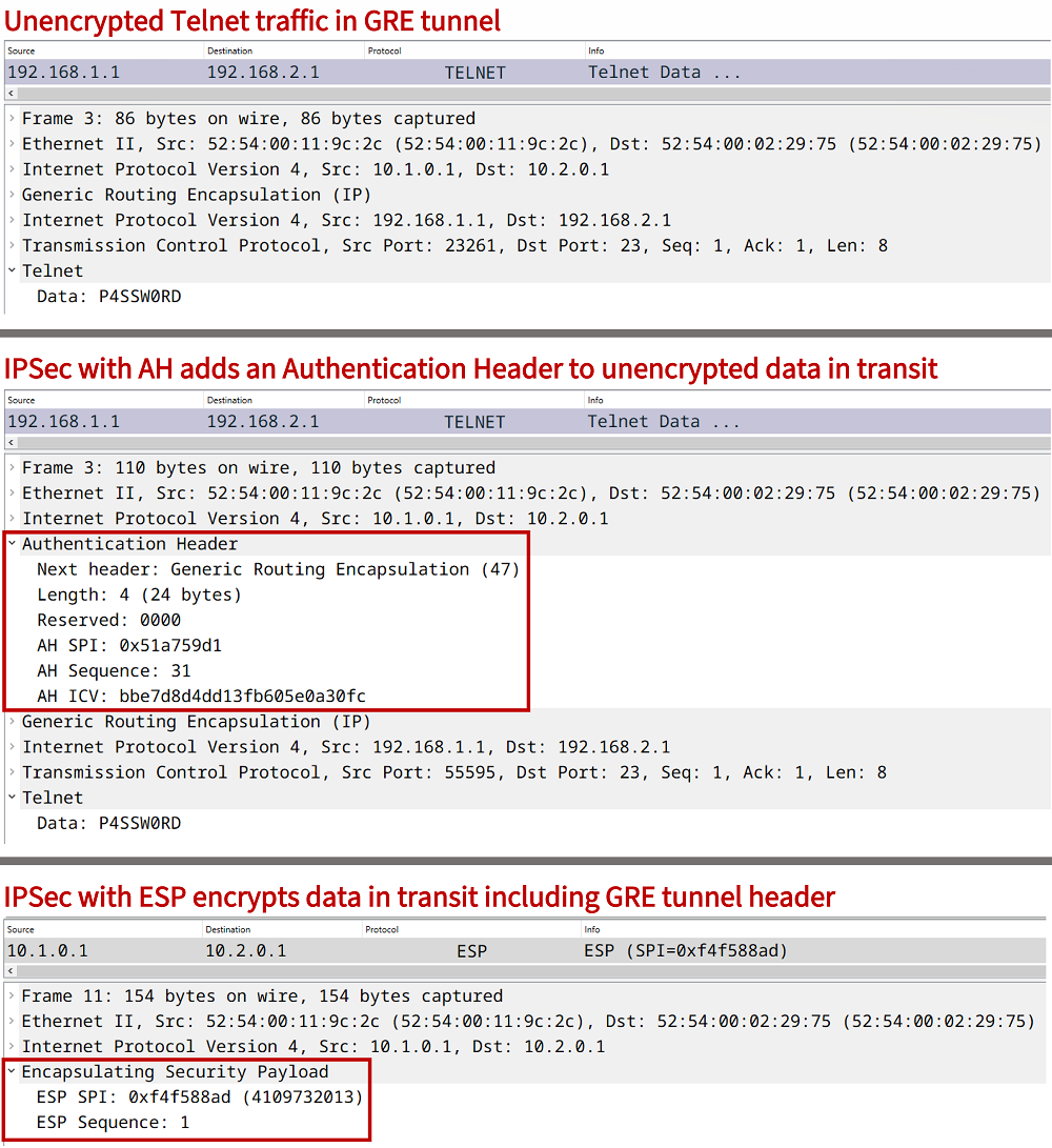
IPSec stands for Internet Protocol Security, and includes a group of protocols that work together to ensure the authenticated and encrypted transmission of data across an unsecured network. IPSec works at the OSI Model Layer-3 which is the network layer, and it is commonly used in site-to-site Virtual Private Networks (VPN). IPsec and GRE tunnel encapsulation are often combined to securely deliver data in transit.
The primary use case of IPSec is to encrypt data in transit between two endpoints. This is achieved by negotiating a Security Association (SA) between the endpoints of the IPSec tunnel. An SA includes the specific paramaters (for example pre-shared key and encryption algorithm) agreed upon by the tunnel endpoints.
IPSec can also be used without the GRE tunneling mechanism, for example by deploying GETVPN or by configuring the IPsec IPv4 tunnel mode under the virtual interface as shown in the configuration below.
R1>
R1>enable
R1#configure terminal
Enter configuration commands, one per line.  End with CNTL/Z.
R1(config)#
R1(config)#interface Tunnel10
R1(config-if)#ip address 192.168.0.1 255.255.255.252
R1(config-if)#tunnel source 10.1.0.1
R1(config-if)#tunnel mode ipsec ipv4
R1(config-if)#tunnel destination 10.1.0.2
R1(config-if)#tunnel protection ipsec profile CRYPTO-IPSEC-PROFILE
R1(config-if)#exit
R1(config)#exit
R1#
As a result of the above configuration, an IP-in-IP tunnel is created using IPSec. A GRE header is not inserted in tunneled packets. The following capture shows such an example with IPSec Authentication Header (AH). Notice, the "Next header" value is set to IP-in-IP.

What is the difference between IKEv1 and IKEv2?
Although IKEv1 is still commonly deployed, it is a deprecated technology standard since April 2023, and provides outdated security measures detailed in RFC 9395. The following is a quote highlighting a section from the RFC.
As IKEv1 is deprecated, systems running IKEv1 should be upgraded and reconfigured to run IKEv2. Systems that support IKEv1 but not IKEv2 are most likely also unsuitable candidates for continued operation for the following reasons:
- IKEv1 development ceased over a decade ago, and no new work will happen. This poses the risk of unmaintained code in an otherwise supported product, which can result in security vulnerabilities.
- A number of IKEv1 systems have reached their End of Life and, therefore, will never be patched by the vendor if a vulnerability is found.
RFC 9395, Deprecation of the Internet Key Exchange Version 1 (IKEv1) Protocol and Obsoleted Algorithms
There are many differences outlined in the RFC, such as IKEv2's capability to use the Extensible Authentication Protocol (EAP) framework which allows for a AAA remote authentication server. Also, in the following router outputs it is visible that with IKEv2 there is only a single SA established, instead of two SAs established with IKEv1.
| IKE version | Output from router |
|---|---|
| IKEv1 | R1#show crypto session Crypto session current status Interface: Tunnel10 Session status: UP-ACTIVE Peer: 10.1.0.2 port 500 Session ID: 0 IKEv1 SA: local 10.1.0.1/500 remote 10.1.0.2/500 Active Session ID: 0 IKEv1 SA: local 10.1.0.1/500 remote 10.1.0.2/500 Active IPSEC FLOW: permit 47 host 10.1.0.1 host 10.1.0.2 Active SAs: 6, origin: crypto map |
| IKEv2 | R1#show crypto session Crypto session current status Interface: Tunnel10 Profile: CRYPTO-IKEV2-PROFILE Session status: UP-ACTIVE Peer: 10.1.0.2 port 500 Session ID: 1 IKEv2 SA: local 10.1.0.1/500 remote 10.1.0.2/500 Active IPSEC FLOW: permit 47 host 10.1.0.1 host 10.1.0.2 Active SAs: 2, origin: crypto map |
IPSec IKEv1 tunnel setup explained and configured
In this example scenario two Sites are connected through the internet. In order to establish a secure and encrypted connection, a site-to-site IPSec tunnel is configured between R1 and R2. This is also called a LAN-to-LAN, L2L, or gateway-to-gateway tunnel. The IPSec tunnel in this example uses the GRE encapsulation method. The following table provides an overview of the encrypted IPSec tunnel negotiation process.
| Status | Description |
|---|---|
| Before negotiation | It is important that the GRE tunnel endpoints are able to reach each other through the transport network. Also, the transport network (e.g. Internet Provider) needs to allow traffic on UDP port 500 or on UDP port 4500 (for IPSec NAT-Traversal). |
| IKE Phase 1 |
The purpose of IKE Phase 1 is to create a secure and authenticated control channel between tunnel endpoints, and it is the first step to enabling secure data transfer. IKE Phase 1 (also referred to as ISAKMP Phase 1) uses UDP port 500 and includes the Diffie–Hellman (DH) secure key exchange mechanism to create a shared (symmetric) key between two tunnel endpoints. This shared key is used for data encryption.
When configuring an IKE Phase 1 policy five parameters (attributes) need to be defined. These are listed below.
|
| IKE Phase 2 | IKE Phase 2 is also called Quick Mode, and it uses the (Diffie-Hellman) shared secret key created in Phase 1 to encrypt user data packets. In other words, while IKE Phase 1 establishes the IPSec control channel, IKE Phase 2 establishes the data channel to transfer end-user traffic. The IKE Phase 2 parameters are configured using a transform-set which is attached to an IPSec profile. |
| After negotiation | Data in transit is encrypted in the IPSec tunnel. Specifically, it depends on whether IPSec data encryption (Encapsulating Security Payload - ESP) or data integrity (Authentication Header - AH) have been configured. IPSec AH can be integrated into other protocols, for example OSPFv3 authentication uses it. |

Configuration:
R1
R1#show run int Gi0/0 | sec int
interface GigabitEthernet0/0
 description ** to internet provider **
 ip address 10.1.0.1 255.255.255.252
 duplex auto
 speed auto
 media-type rj45

R1#show run int Gi0/1 | sec int
interface GigabitEthernet0/1
 description ** to Host1 **
 ip address 192.168.1.2 255.255.255.0
 duplex auto
 speed auto
 media-type rj45

R1#show run int Tu10 | sec int
interface Tunnel10
 description ** GRE/IPSec static VTI **
 ip address 172.16.0.1 255.255.255.252
 tunnel source GigabitEthernet0/0
 tunnel destination 10.2.0.1
 tunnel protection ipsec profile CRYPTO-PROFILE

R1#show run | sec ^crypto
crypto isakmp policy 10
 authentication pre-share
crypto isakmp key p4ssw0rd address 10.2.0.1
crypto ipsec transform-set CRYPTO-TRANSFORM esp-aes
 mode transport
crypto ipsec profile CRYPTO-PROFILE
 set transform-set CRYPTO-TRANSFORM

R1#show run | sec router
router ospf 10
 router-id 1.1.1.1
 network 172.16.0.0 0.0.0.3 area 0
 network 192.168.1.0 0.0.0.255 area 0

R1#show run | sec ip route
ip route 0.0.0.0 0.0.0.0 GigabitEthernet0/0 10.1.0.2
R2
R2#show run int Gi0/0 | sec int
interface GigabitEthernet0/0
 description ** to internet provider **
 ip address 10.2.0.1 255.255.255.252
 duplex auto
 speed auto
 media-type rj45

R2#show run int Gi0/1 | sec int
interface GigabitEthernet0/1
 description ** to Host2 **
 ip address 192.168.2.2 255.255.255.0
 duplex auto
 speed auto
 media-type rj45

R2#show run int Tu10 | sec int
interface Tunnel10
 description ** GRE/IPSec static VTI **
 ip address 172.16.0.2 255.255.255.252
 tunnel source GigabitEthernet0/0
 tunnel destination 10.1.0.1
 tunnel protection ipsec profile CRYPTO-PROFILE

R2#show run | sec ^crypto
crypto isakmp policy 10
 authentication pre-share
crypto isakmp key p4ssw0rd address 10.1.0.1
crypto ipsec transform-set CRYPTO-TRANSFORM esp-aes
 mode transport
crypto ipsec profile CRYPTO-PROFILE
 set transform-set CRYPTO-TRANSFORM

R2#show run | sec router
router ospf 10
 router-id 2.2.2.2
 network 172.16.0.0 0.0.0.3 area 0
 network 192.168.2.0 0.0.0.255 area 0

R2#show run | sec ip route
ip route 0.0.0.0 0.0.0.0 GigabitEthernet0/0 10.2.0.2
R1#show crypto session brief
Status: A- Active, U - Up, D - Down, I - Idle, S - Standby, N - Negotiating
        K - No IKE
ivrf = (none)
Peer            I/F          Username        Group/Phase1_id          Uptime   Status
10.2.0.1        Tu10                         10.2.0.1                 01:26:16 UA      « IPSec tunnel is Up and Active
10.2.0.1        Tu10                         10.2.0.1                 01:26:16 UA


R1#show crypto session
Crypto session current status

Interface: Tunnel10
Session status: UP-ACTIVE
Peer: 10.2.0.1 port 500
  Session ID: 0
  IKEv1 SA: local 10.1.0.1/500 remote 10.2.0.1/500 Active        « IKEv1 Security Association is used
  Session ID: 0
  IKEv1 SA: local 10.1.0.1/500 remote 10.2.0.1/500 Active
  IPSEC FLOW: permit 47 host 10.1.0.1 host 10.2.0.1
        Active SAs: 2, origin: crypto map


Host1#ping 192.168.2.1
Type escape sequence to abort.
Sending 5, 100-byte ICMP Echos to 192.168.2.1, timeout is 2 seconds:
!!!!!
Success rate is 100 percent (5/5), round-trip min/avg/max = 88/88/90 ms       « Host1 can ping Host2 through


Host1#trace 192.168.2.1 probe 1
Type escape sequence to abort.
Tracing the route to 192.168.2.1
VRF info: (vrf in name/id, vrf out name/id)
  1 192.168.1.2 1 msec
  2 172.16.0.2 89 msec            « Host1 uses the IPSec tunnel to reach Host2
  3 192.168.2.1 89 msec
As visible above, Host1 and Host2 can communicate through the IPSec tunnel, and the data flow is encrypted while transiting the unsecured portion of the network. An important part of this topology is the routing protocol OSPF, which is configured between Site 1 and Site 2 over the IPSec tunnel. OSPF enables R1 and R2 to securely learn the networks from each site.
R1#show ip ospf neighbor

Neighbor ID     Pri   State           Dead Time   Address         Interface
2.2.2.2           0   FULL/  -        00:00:30    172.16.0.2      Tunnel10      « OSPF neighborship across the Tunnel interface


R1#show ip route ospf | beg Ga
Gateway of last resort is 10.1.0.2 to network 0.0.0.0

O     192.168.2.0/24 [110/1001] via 172.16.0.2, 01:33:01, Tunnel10          « Site 2 route learnt through the Tunnel interface


R1#show ip route 192.168.2.0
Routing entry for 192.168.2.0/24
  Known via "ospf 10", distance 110, metric 1001, type intra area
  Last update from 172.16.0.2 on Tunnel10, 01:33:12 ago          « To reach Site 2, the next-hop is the Tunnel interface
  Routing Descriptor Blocks:
  * 172.16.0.2, from 2.2.2.2, 01:33:12 ago, via Tunnel10
      Route metric is 1001, traffic share count is 1
IPSec GRE tunnel in VRF (only IVRF) configuration
In this example scenario, Site 1 and Site 2 are configured in "VRF-BLUE". The two sites communicate in VRF-Blue over a GRE/IPSec tunnel. In other words, within the IPSec tunnel the inside VRF is called VRF-BLUE. The technical term inside VRF or IVRF signifies the fact that the GRE tunnel overlay is configured to forward traffic in a particular VRF.
The internet-facing physical links (underlay) of R1 and R2 are in the global routing table, and are not assigned to any particular VRF. Only the IPSec tunnel carries traffic in VRF-BLUE. Notice also, the routing protocol OSPF is configured within VRF-BLUE.

Configuration:
R1
R1#show run | sec ^vrf
vrf definition VRF-BLUE
 rd 1:1
 !
 address-family ipv4
 exit-address-family

R1#show run int Gi0/0 | sec int
interface GigabitEthernet0/0
 description ** to internet provider **
 ip address 10.1.0.1 255.255.255.252
 duplex auto
 speed auto
 media-type rj45

R1#show run int Gi0/1 | sec int
interface GigabitEthernet0/1
 description ** to Host1 **
 no ip address
 duplex auto
 speed auto
 media-type rj45

R1#show run int Gi0/1.10 | sec int
interface GigabitEthernet0/1.10
 description ** to Host1 in VRF-BLUE **
 encapsulation dot1Q 10
 vrf forwarding VRF-BLUE
 ip address 192.168.1.2 255.255.255.0

R1#show run int Tu10 | sec int
interface Tunnel10
 description ** GRE/IPSec static VTI in VRF-BLUE **
 vrf forwarding VRF-BLUE
 ip address 172.16.0.1 255.255.255.252
 tunnel source GigabitEthernet0/0
 tunnel destination 10.2.0.1
 tunnel protection ipsec profile CRYPTO-PROFILE

R1#show run | sec ^crypto
crypto isakmp policy 10
 authentication pre-share
crypto isakmp key p4ssw0rd address 10.2.0.1
crypto ipsec transform-set CRYPTO-TRANSFORM esp-aes
 mode transport
crypto ipsec profile CRYPTO-PROFILE
 set transform-set CRYPTO-TRANSFORM

R1#show run | sec router
router ospf 10 vrf VRF-BLUE
 router-id 1.1.1.1
 network 172.16.0.0 0.0.0.3 area 0
 network 192.168.1.0 0.0.0.255 area 0

R1#show run | sec ip route
ip route 0.0.0.0 0.0.0.0 GigabitEthernet0/0 10.1.0.2
R2
R2#show run | sec ^vrf
vrf definition VRF-BLUE
 rd 1:1
 !
 address-family ipv4
 exit-address-family

R2#show run int Gi0/0 | sec int
interface GigabitEthernet0/0
 description ** to internet provider **
 ip address 10.2.0.1 255.255.255.252
 duplex auto
 speed auto
 media-type rj45

R2#show run int Gi0/1 | sec int
interface GigabitEthernet0/1
 description ** to Host2 **
 no ip address
 duplex auto
 speed auto
 media-type rj45

R2#show run int Gi0/1.10 | sec int
interface GigabitEthernet0/1.10
 description ** to Host2 in VRF-Blue **
 encapsulation dot1Q 10
 vrf forwarding VRF-BLUE
 ip address 192.168.2.2 255.255.255.0

R2#show run int Tu10 | sec int
interface Tunnel10
 description ** GRE/IPSec static VTI in VRF-BLUE **
 vrf forwarding VRF-BLUE
 ip address 172.16.0.2 255.255.255.252
 tunnel source GigabitEthernet0/0
 tunnel destination 10.1.0.1
 tunnel protection ipsec profile CRYPTO-PROFILE

R2#show run | sec ^crypto
crypto isakmp policy 10
 authentication pre-share
crypto isakmp key p4ssw0rd address 10.1.0.1
crypto ipsec transform-set CRYPTO-TRANSFORM esp-aes
 mode transport
crypto ipsec profile CRYPTO-PROFILE
 set transform-set CRYPTO-TRANSFORM

R2#show run | sec router
router ospf 10 vrf VRF-BLUE
 router-id 2.2.2.2
 network 172.16.0.0 0.0.0.3 area 0
 network 192.168.2.0 0.0.0.255 area 0

R2#show run | sec ip route
ip route 0.0.0.0 0.0.0.0 GigabitEthernet0/0 10.2.0.2
R1#show crypto session br
Status: A- Active, U - Up, D - Down, I - Idle, S - Standby, N - Negotiating
        K - No IKE
ivrf = VRF-BLUE
Peer            I/F          Username        Group/Phase1_id          Uptime   Status
10.2.0.1        Tu10                         10.2.0.1                 00:21:45 UA        « IPSec crypto session is Up and Active
10.2.0.1        Tu10                         10.2.0.1                 00:21:45 UA


R1#show crypto session detail
Crypto session current status

Code: C - IKE Configuration mode, D - Dead Peer Detection
K - Keepalives, N - NAT-traversal, T - cTCP encapsulation
X - IKE Extended Authentication, F - IKE Fragmentation
R - IKE Auto Reconnect, U - IKE Dynamic Route Update
S - SIP VPN

Interface: Tunnel10
Uptime: 00:21:52
Session status: UP-ACTIVE
Peer: 10.2.0.1 port 500 fvrf: (none) ivrf: VRF-BLUE             « The inside VRF is VRF-BLUE
      Phase1_id: 10.2.0.1
      Desc: (none)
  Session ID: 0
  IKEv1 SA: local 10.1.0.1/500 remote 10.2.0.1/500 Active       « IPSec IKEv1 is being used
          Capabilities:(none) connid:1007 lifetime:23:38:06
  Session ID: 0
  IKEv1 SA: local 10.1.0.1/500 remote 10.2.0.1/500 Active
          Capabilities:(none) connid:1008 lifetime:23:38:10
  IPSEC FLOW: permit 47 host 10.1.0.1 host 10.2.0.1
        Active SAs: 4, origin: crypto map
        Inbound:  #pkts dec'ed 151 drop 0 life (KB/Sec) 4371268/2290
        Outbound: #pkts enc'ed 152 drop 0 life (KB/Sec) 4371268/2290


Host1#ping 192.168.2.1
Type escape sequence to abort.
Sending 5, 100-byte ICMP Echos to 192.168.2.1, timeout is 2 seconds:
!!!!!
Success rate is 100 percent (5/5), round-trip min/avg/max = 91/92/93 ms            « Host1 can ping Host2


Host1#trace 192.168.2.1 probe 1
Type escape sequence to abort.
Tracing the route to 192.168.2.1
VRF info: (vrf in name/id, vrf out name/id)
  1 192.168.1.2 3 msec
  2 172.16.0.2 91 msec                  « Host1 uses the IPSec tunnel interface to reach Host2
  3 192.168.2.1 92 msec
IPSec IKEv1 improved security configuration
An IPSec Tunnel's level of security can be manually configured, and adjusted based on predetermined requirements or a coporate security policy. The following are examples in this scenario to show some of the IPSec details that can be adjusted:
- The command set pfs group2 configures Perfect Forward Secrecy (PFS) which generates new Diffie-Hellman (DH) keys for each newly established SA (IKE Phase 2), this includes regular tunnel rekeying. Without PFS, the DH key from Phase 1 is used in Phase 2.
- The command match identity address 10.2.0.1 255.255.255.255 (on R1) hardcodes the IPsec peer identity, needs to be R2 interface Gi0/0 IP address.
- The command set security-association lifetime configures a data limit or time limit value before the SA rekeying happens, or in other words the IPSec tunnel is rebuilt each time the configured value expires or the data value is exceeded.
- The command crypto isakmp keepalive 15 5 configures Dead Peer Detection (DPD) to monitor the liveliness of the IPSec peer.

Configuration:
R1
R1#show run int Gi0/0 | sec int
interface GigabitEthernet0/0
 description ** to internet provider **
 ip address 10.1.0.1 255.255.255.252
 duplex auto
 speed auto
 media-type rj45

R1#show run int Gi0/1 | sec int
interface GigabitEthernet0/1
 description ** to Host1 **
 ip address 192.168.1.2 255.255.255.0
 duplex auto
 speed auto
 media-type rj45

R1#show run int Tu10 | sec int
interface Tunnel10
 description ** GRE/IPSec static VTI **
 ip address 172.16.0.1 255.255.255.252
 tunnel source GigabitEthernet0/0
 tunnel destination 10.2.0.1
 tunnel protection ipsec profile IPSEC-PROFILE

R1#show run | sec ^crypto
crypto keyring CRYPTO-KEY
  pre-shared-key address 10.2.0.1 key p4ssw0rd.123
crypto isakmp policy 10
 encr aes 256
 hash sha256
 authentication pre-share
 group 2
 lifetime 43200
crypto isakmp keepalive 15 5
crypto isakmp profile ISAKMP-PROFILE
   keyring CRYPTO-KEY
   match identity address 10.2.0.1 255.255.255.255
   local-address GigabitEthernet0/0
crypto ipsec transform-set CRYPTO-TRANSFORM esp-aes 256
 mode transport
crypto ipsec profile IPSEC-PROFILE
 set security-association lifetime kilobytes 1000000
 set security-association lifetime seconds 43200
 set security-association idle-time 60
 set security-association replay window-size 512
 set transform-set CRYPTO-TRANSFORM
 set pfs group2
 set isakmp-profile ISAKMP-PROFILE

R1#show run | sec router
router ospf 10
 router-id 1.1.1.1
 network 172.16.0.0 0.0.0.3 area 0
 network 192.168.1.0 0.0.0.255 area 0

R1#show run | sec ip route
ip route 0.0.0.0 0.0.0.0 GigabitEthernet0/0 10.1.0.2
R2
R2#show run int Gi0/0 | sec int
interface GigabitEthernet0/0
 description ** to internet provider **
 ip address 10.2.0.1 255.255.255.252
 duplex auto
 speed auto
 media-type rj45

R2#show run int Gi0/1 | sec int
interface GigabitEthernet0/1
 description ** to Host2 **
 ip address 192.168.2.2 255.255.255.0
 duplex auto
 speed auto
 media-type rj45

R2#show run int Tu10 | sec int
interface Tunnel10
 description ** GRE/IPSec static VTI **
 ip address 172.16.0.2 255.255.255.252
 tunnel source GigabitEthernet0/0
 tunnel destination 10.1.0.1
 tunnel protection ipsec profile IPSEC-PROFILE

R2#show run | sec ^crypto
crypto keyring CRYPTO-KEY
  pre-shared-key address 10.1.0.1 key p4ssw0rd.123
crypto isakmp policy 10
 encr aes 256
 hash sha256
 authentication pre-share
 group 2
 lifetime 43200
crypto isakmp keepalive 15 5
crypto isakmp profile ISAKMP-PROFILE
   keyring CRYPTO-KEY
   match identity address 10.1.0.1 255.255.255.255
   local-address GigabitEthernet0/0
crypto ipsec transform-set CRYPTO-TRANSFORM esp-aes 256
 mode transport
crypto ipsec profile IPSEC-PROFILE
 set security-association lifetime kilobytes 1000000
 set security-association lifetime seconds 43200
 set security-association idle-time 60
 set security-association replay window-size 512
 set transform-set CRYPTO-TRANSFORM
 set pfs group2
 set isakmp-profile ISAKMP-PROFILE

R2#show run | sec router
router ospf 10
 router-id 2.2.2.2
 network 172.16.0.0 0.0.0.3 area 0
 network 192.168.2.0 0.0.0.255 area 0

R2#show run | sec ip route
ip route 0.0.0.0 0.0.0.0 GigabitEthernet0/0 10.2.0.2
R1#show crypto session brief
Status: A- Active, U - Up, D - Down, I - Idle, S - Standby, N - Negotiating
        K - No IKE
ivrf = (none)
Peer            I/F          Username        Group/Phase1_id          Uptime   Status
10.2.0.1        Tu10                         10.2.0.1                 00:30:01 UA        « The IPSec tunnel is Up and Active


R1#show crypto session
Crypto session current status

Interface: Tunnel10
Profile: ISAKMP-PROFILE                 « This ISAKMP profile is configured and used
Session status: UP-ACTIVE
Peer: 10.2.0.1 port 500
  Session ID: 0
  IKEv1 SA: local 10.1.0.1/500 remote 10.2.0.1/500 Active        « IPSec tunnel uses IKEv1
  IPSEC FLOW: permit 47 host 10.1.0.1 host 10.2.0.1
        Active SAs: 2, origin: crypto map


Host1#ping 192.168.2.1
Type escape sequence to abort.
Sending 5, 100-byte ICMP Echos to 192.168.2.1, timeout is 2 seconds:
!!!!!
Success rate is 100 percent (5/5), round-trip min/avg/max = 88/88/89 ms         « Host1 can ping Host2


Host1#trace 192.168.2.1 probe 1
Type escape sequence to abort.
Tracing the route to 192.168.2.1
VRF info: (vrf in name/id, vrf out name/id)
  1 192.168.1.2 1 msec
  2 172.16.0.2 88 msec                       « The IPSec tunnel between R1 and R2 is used
  3 192.168.2.1 89 msec
The following output shows a default IPSec profile and also the one configured for this example scenario.
R1#show crypto ipsec profile
IPSEC profile IPSEC-PROFILE
        ISAKMP Profile: ISAKMP-PROFILE
        Security association lifetime: 1000000 kilobytes/43200 seconds
        Security association idletime: 60 seconds
        Responder-Only (Y/N): N
        PFS (Y/N): Y                          « Perfect Forward Secrecy (PFS) is enabled
        DH group:  group2
        Mixed-mode : Disabled
        Transform sets={
                CRYPTO-TRANSFORM:  { esp-256-aes  } ,
        }
        Antireplay window size = 512

IPSEC profile default
        Security association lifetime: 4608000 kilobytes/3600 seconds
        Responder-Only (Y/N): N
        PFS (Y/N): N
        Mixed-mode : Disabled
        Transform sets={
                default:  { esp-aes esp-sha-hmac  } ,
Notice in the above output from R1 that the Diffie–Hellman Group (DH group) 2 is used in this example scenario. However, in a production network for improved security this would likely be changed to DH group 19, 20, 21 or 24. Additionally, instead of using a pre-shared key simple password authentication, R1 and R2 could use certificate-based authentication and encryption based on the Public Key Infrastructure (PKI).
IPSec with FVRF and IVRF configuration
In this example scenario, Site 1 and Site 2 are connected through an IKEv1 IPSec overlay tunnel in VRF-BLUE. Meanwhile, the underlay network is configured in VRF-ORANGE. As a result, there are two VRFs working together in this topology.
The IPSec tunnel needs to be instructed to use VRF-ORANGE as the tunnel source. This makes VRF-ORANGE the Front Door VRF, or FVRF. And VRF-BLUE is the Inside VRF, or IVRF.
The tunnel interface command tunnel vrf VRF-ORANGE instructs the GRE Tunnel to use VRF-ORANGE as its Front Door VRF. And this information also needs to be reflected in the IPSec configuration. The details are shown in the following image.

Configuration:
R1
R1#show run | sec ^vrf
vrf definition VRF-BLUE
 description ** Inside VRF (IVRF) - IPSec tunnel **
 rd 1:1
 !
 address-family ipv4
 exit-address-family
vrf definition VRF-ORANGE
 description ** Front Door VRF (FVRF) - to internet **
 rd 2:2
 !
 address-family ipv4
 exit-address-family

R1#show run int Gi0/1 | sec int
interface GigabitEthernet0/1
 description ** to Host1 **
 no ip address
 duplex auto
 speed auto
 media-type rj45

R1#show run int Gi0/1.10 | sec int
interface GigabitEthernet0/1.10
 description ** to Host1 in VRF-BLUE **
 encapsulation dot1Q 10
 vrf forwarding VRF-BLUE
 ip address 192.168.1.2 255.255.255.0

R1#show run int Gi0/0 | sec int
interface GigabitEthernet0/0
 description ** to internet provider **
 no ip address
 duplex auto
 speed auto
 media-type rj45

R1#show run int Gi0/0.10 | sec int
interface GigabitEthernet0/0.10
 description ** to internet provider - FVRF **
 encapsulation dot1Q 10
 vrf forwarding VRF-ORANGE
 ip address 10.1.0.1 255.255.255.252

R1#show run int Tu10 | sec int
interface Tunnel10
 description ** GRE/IPSec static VTI in VRF-BLUE **
 vrf forwarding VRF-BLUE
 ip address 172.16.0.1 255.255.255.252
 tunnel source GigabitEthernet0/0.10
 tunnel destination 10.2.0.1
 tunnel vrf VRF-ORANGE
 tunnel protection ipsec profile CRYPTO-PROFILE

R1#show run | sec ^crypto
crypto keyring CRYPTO-KEY vrf VRF-ORANGE
  pre-shared-key address 10.2.0.1 255.255.255.252 key p4ssw0rd.123
crypto isakmp policy 10
 authentication pre-share
crypto isakmp profile CRYPTO-IKEV1-PROFILE
   keyring CRYPTO-KEY
   match identity address 10.2.0.1 255.255.255.252 VRF-ORANGE
crypto ipsec transform-set CRYPTO-TRANSFORM esp-aes
 mode transport
crypto ipsec profile CRYPTO-PROFILE
 set transform-set CRYPTO-TRANSFORM

R1#show run | sec ^router
router ospf 10 vrf VRF-BLUE
 router-id 1.1.1.1
 network 172.16.0.0 0.0.0.3 area 0
 network 192.168.1.0 0.0.0.255 area 0

R1#show run | sec ip route
ip route vrf VRF-ORANGE 0.0.0.0 0.0.0.0 GigabitEthernet0/0.10 10.1.0.2
R2
R2#show run | sec ^vrf
vrf definition VRF-BLUE
 description ** Inside VRF (IVRF) - IPSec tunnel **
 rd 1:1
 !
 address-family ipv4
 exit-address-family
vrf definition VRF-ORANGE
 description ** Front Door VRF (FVRF) - to internet **
 rd 2:2
 !
 address-family ipv4
 exit-address-family

R2#show run int Gi0/1 | sec int
interface GigabitEthernet0/1
 description ** to Host2 **
 no ip address
 duplex auto
 speed auto
 media-type rj45

R2#show run int Gi0/1.10 | sec int
interface GigabitEthernet0/1.10
 description ** to Host2 in VRF-BLUE **
 encapsulation dot1Q 10
 vrf forwarding VRF-BLUE
 ip address 192.168.2.2 255.255.255.0

R2#show run int Gi0/0 | sec int
interface GigabitEthernet0/0
 description ** to internet provider **
 no ip address
 duplex auto
 speed auto
 media-type rj45

R2#show run int Gi0/0.10 | sec int
interface GigabitEthernet0/0.10
 description ** to internet provider - FVRF **
 encapsulation dot1Q 10
 vrf forwarding VRF-ORANGE
 ip address 10.2.0.1 255.255.255.252

R2#show run int Tu10 | sec int
interface Tunnel10
 description ** GRE/IPSec static VTI in VRF-BLUE **
 vrf forwarding VRF-BLUE
 ip address 172.16.0.2 255.255.255.252
 tunnel source GigabitEthernet0/0.10
 tunnel destination 10.1.0.1
 tunnel vrf VRF-ORANGE
 tunnel protection ipsec profile CRYPTO-PROFILE

R2#show run | sec ^crypto
crypto keyring CRYPTO-KEY vrf VRF-ORANGE
  pre-shared-key address 10.1.0.1 255.255.255.252 key p4ssw0rd.123
crypto isakmp policy 10
 authentication pre-share
crypto isakmp profile CRYPTO-IKEV1-PROFILE
   keyring CRYPTO-KEY
   match identity address 10.1.0.1 255.255.255.252 VRF-ORANGE
crypto ipsec transform-set CRYPTO-TRANSFORM esp-aes
 mode transport
crypto ipsec profile CRYPTO-PROFILE
 set transform-set CRYPTO-TRANSFORM

R2#show run | sec ^router
router ospf 10 vrf VRF-BLUE
 router-id 2.2.2.2
 network 172.16.0.0 0.0.0.3 area 0
 network 192.168.2.0 0.0.0.255 area 0

R2#show run | sec ^ip route
ip route vrf VRF-ORANGE 0.0.0.0 0.0.0.0 GigabitEthernet0/0.10 10.2.0.2
R1#show crypto session brief
Status: A- Active, U - Up, D - Down, I - Idle, S - Standby, N - Negotiating
        K - No IKE
ivrf = VRF-BLUE
Peer            I/F          Username        Group/Phase1_id          Uptime   Status
10.2.0.1        Tu10                         10.2.0.1                 00:23:41 UA          « IPSec tunnel is Up and Active
10.2.0.1        Tu10                         10.2.0.1                 00:23:41 UA


R1#show crypto session detail | begin Interface
Interface: Tunnel10
Profile: CRYPTO-IKEV1-PROFILE
Uptime: 00:24:08
Session status: UP-ACTIVE
Peer: 10.2.0.1 port 500 fvrf: VRF-ORANGE ivrf: VRF-BLUE         « FVRF and IVRF are visible
      Phase1_id: 10.2.0.1
      Desc: (none)
  Session ID: 0
  IKEv1 SA: local 10.1.0.1/500 remote 10.2.0.1/500 Active       « IKEv1 is used
          Capabilities:(none) connid:1003 lifetime:23:35:50
  Session ID: 0
  IKEv1 SA: local 10.1.0.1/500 remote 10.2.0.1/500 Active
          Capabilities:(none) connid:1004 lifetime:23:35:58
  IPSEC FLOW: permit 47 host 10.1.0.1 host 10.2.0.1
        Active SAs: 2, origin: crypto map
        Inbound:  #pkts dec'ed 168 drop 0 life (KB/Sec) 4365425/2158
        Outbound: #pkts enc'ed 168 drop 0 life (KB/Sec) 4365425/2158


Host1#ping 192.168.2.1
Type escape sequence to abort.
Sending 5, 100-byte ICMP Echos to 192.168.2.1, timeout is 2 seconds:
!!!!!
Success rate is 100 percent (5/5), round-trip min/avg/max = 90/90/92 ms


Host1#trace 192.168.2.1 probe 1
Type escape sequence to abort.
Tracing the route to 192.168.2.1
VRF info: (vrf in name/id, vrf out name/id)
  1 192.168.1.2 3 msec
  2 172.16.0.2 89 msec
  3 192.168.2.1 90 msec
IPSec IKEv2 configuration
In this example scenario, Site 1 and Site 2 are connected through an IPSec tunnel which uses IKEv2. Compared to IKEv1, IKEv2 offers several benefits including improved default security features and a lower protocol overhead. In order to enable communication between the two sites across the encrypted IPSec tunnel, the routing protocol OSPF is configured.

Configuration:
R1
R1#show run int Gi0/0 | sec int
interface GigabitEthernet0/0
 description ** to internet provider **
 ip address 10.1.0.1 255.255.255.252
 duplex auto
 speed auto
 media-type rj45

R1#show run int Gi0/1 | sec int
interface GigabitEthernet0/1
 description ** to Host1 **
 ip address 192.168.1.2 255.255.255.0
 duplex auto
 speed auto
 media-type rj45

R1#show run int Tu10 | sec int
interface Tunnel10
 description ** GRE/IPSec static VTI **
 ip address 172.16.0.1 255.255.255.252
 tunnel source GigabitEthernet0/0
 tunnel destination 10.2.0.1
 tunnel protection ipsec profile CRYPTO-IPSEC-PROFILE

R1#show run | sec ^crypto
crypto ikev2 proposal CRYPTO-PROPOSAL
 encryption aes-cbc-256
 integrity sha256
 group 1
crypto ikev2 policy CRYPTO-POLICY
 match address local 10.1.0.1
 proposal CRYPTO-PROPOSAL
crypto ikev2 keyring CRYPTO-KEYRING
 peer KEY-PEER
  address 10.2.0.1
  pre-shared-key p4ssw0rd.123
 !
crypto ikev2 profile CRYPTO-IKEV2-PROFILE
 match identity remote address 10.2.0.1 255.255.255.255
 authentication remote pre-share
 authentication local pre-share
 keyring local CRYPTO-KEYRING
crypto ipsec transform-set CRYPTO-TRANSFORM esp-aes
 mode transport
crypto ipsec profile CRYPTO-IPSEC-PROFILE
 set transform-set CRYPTO-TRANSFORM
 set ikev2-profile CRYPTO-IKEV2-PROFILE

R1#show run | sec router
router ospf 10
 router-id 1.1.1.1
 network 172.16.0.0 0.0.0.3 area 0
 network 192.168.1.0 0.0.0.255 area 0

R1#show run | sec ip route
ip route 0.0.0.0 0.0.0.0 GigabitEthernet0/0 10.1.0.2
R2
R2#show run int Gi0/0 | sec int
interface GigabitEthernet0/0
 description ** to internet provider **
 ip address 10.2.0.1 255.255.255.252
 duplex auto
 speed auto
 media-type rj45

R2#show run int Gi0/1 | sec int
interface GigabitEthernet0/1
 description ** to Host2 **
 ip address 192.168.2.2 255.255.255.0
 duplex auto
 speed auto
 media-type rj45

R2#show run int Tu10 | sec int
interface Tunnel10
 description ** GRE/IPSec static VTI **
 ip address 172.16.0.2 255.255.255.252
 tunnel source GigabitEthernet0/0
 tunnel destination 10.1.0.1
 tunnel protection ipsec profile CRYPTO-IPSEC-PROFILE

R2#show run | sec ^crypto
crypto ikev2 proposal CRYPTO-PROPOSAL
 encryption aes-cbc-256
 integrity sha256
 group 1
crypto ikev2 policy CRYPTO-POLICY
 match address local 10.2.0.1
 proposal CRYPTO-PROPOSAL
crypto ikev2 keyring CRYPTO-KEYRING
 peer KEY-PEER
  address 10.1.0.1
  pre-shared-key p4ssw0rd.123
 !
crypto ikev2 profile CRYPTO-IKEV2-PROFILE
 match identity remote address 10.1.0.1 255.255.255.255
 authentication remote pre-share
 authentication local pre-share
 keyring local CRYPTO-KEYRING
crypto ipsec transform-set CRYPTO-TRANSFORM esp-aes
 mode transport
crypto ipsec profile CRYPTO-IPSEC-PROFILE
 set transform-set CRYPTO-TRANSFORM
 set ikev2-profile CRYPTO-IKEV2-PROFILE

R2#show run | sec router
router ospf 10
 router-id 2.2.2.2
 network 172.16.0.0 0.0.0.3 area 0
 network 192.168.2.0 0.0.0.255 area 0

R2#show run | sec ip route
ip route 0.0.0.0 0.0.0.0 GigabitEthernet0/0 10.2.0.2
R1#show crypto session brief
Status: A- Active, U - Up, D - Down, I - Idle, S - Standby, N - Negotiating
        K - No IKE
ivrf = (none)
Peer            I/F          Username        Group/Phase1_id          Uptime   Status
10.2.0.1        Tu10                         10.2.0.1                 00:11:53 UA     « IPSec session is Up and Active


R1#show crypto session
Crypto session current status

Interface: Tunnel10
Profile: CRYPTO-IKEV2-PROFILE
Session status: UP-ACTIVE
Peer: 10.2.0.1 port 500
  Session ID: 4
  IKEv2 SA: local 10.1.0.1/500 remote 10.2.0.1/500 Active            « IKEv2 is being used
  IPSEC FLOW: permit 47 host 10.1.0.1 host 10.2.0.1
        Active SAs: 2, origin: crypto map


Host1#ping 192.168.2.1
Type escape sequence to abort.
Sending 5, 100-byte ICMP Echos to 192.168.2.1, timeout is 2 seconds:
!!!!!
Success rate is 100 percent (5/5), round-trip min/avg/max = 88/89/90 ms      « Host1 can ping Host2


Host1#trace 192.168.2.1 probe 1
Type escape sequence to abort.
Tracing the route to 192.168.2.1
VRF info: (vrf in name/id, vrf out name/id)
  1 192.168.1.2 2 msec
  2 172.16.0.2 88 msec                  « Traffic between Host1 and Host2 is routed across the IPSec tunnel
  3 192.168.2.1 89 msec
IPSec IKEv2 FVRF and IVRF configuration
In this example, Site 1 and Site 2 are connected with an IKEv2 IPSec tunnel configured in VRF-BLUE. Notice, that the IPSec tunnel is configured in VRF-BLUE, while the underlay (or transport) network uses the VRF called "VRF-ORANGE". Thus, there are two VRFs working together in this topology. As a result, the IPSec tunnel interface on R1 and R2 needs to be instructed to use VRF-ORANGE as a tunnel source.
This makes VRF-ORANGE the Front Door VRF, or FVRF. And VRF-BLUE is the Inside VRF, or IVRF. The command tunnel vrf VRF-ORANGE is configured under the GRE tunnel interface and instructs it to use VRF-ORANGE as the Front Door VRF. This information also needs to be reflected in the IPSec IKEv2 configuration, shown in the following image.

Configuration:
R1
R1#show run | sec ^vrf
vrf definition VRF-BLUE
 description ** Inside VRF (IVRF) - IPSec tunnel **
 rd 1:1
 !
 address-family ipv4
 exit-address-family
vrf definition VRF-ORANGE
 description ** Front Door VRF (FVRF) - to internet **
 rd 2:2
 !
 address-family ipv4
 exit-address-family

R1#show run int Gi0/1 | sec int
interface GigabitEthernet0/1
 description ** to Host1 **
 no ip address
 duplex auto
 speed auto
 media-type rj45

R1#show run int Gi0/1.10 | sec int
interface GigabitEthernet0/1.10
 description ** to Host1 in VRF-BLUE **
 encapsulation dot1Q 10
 vrf forwarding VRF-BLUE
 ip address 192.168.1.2 255.255.255.0

R1#show run int Gi0/0 | sec int
interface GigabitEthernet0/0
 description ** to internet provider **
 no ip address
 duplex auto
 speed auto
 media-type rj45

R1#show run int Gi0/0.10 | sec int
interface GigabitEthernet0/0.10
 description ** to internet provider - FVRF **
 encapsulation dot1Q 10
 vrf forwarding VRF-ORANGE
 ip address 10.1.0.1 255.255.255.252

R1#show run int Tu10 | sec int
interface Tunnel10
 description ** GRE/IPSec static VTI in VRF-BLUE **
 vrf forwarding VRF-BLUE
 ip address 172.16.0.1 255.255.255.252
 tunnel source GigabitEthernet0/0.10
 tunnel destination 10.2.0.1
 tunnel vrf VRF-ORANGE
 tunnel protection ipsec profile CRYPTO-IPSEC-PROFILE

R1#show run | sec ^crypto
crypto ikev2 proposal CRYPTO-PROPOSAL
 encryption aes-cbc-256
 integrity sha256
 group 1
crypto ikev2 policy CRYPTO-POLICY
 match fvrf VRF-ORANGE
 match address local 10.1.0.1
 proposal CRYPTO-PROPOSAL
crypto ikev2 keyring CRYPTO-KEYRING
 peer KEY-PEER
  address 10.2.0.1
  pre-shared-key p4ssw0rd.123
 !
crypto ikev2 profile CRYPTO-IKEV2-PROFILE
 match fvrf VRF-ORANGE
 match identity remote address 10.2.0.1 255.255.255.255
 authentication remote pre-share
 authentication local pre-share
 keyring local CRYPTO-KEYRING
crypto ipsec transform-set CRYPTO-TRANSFORM esp-aes
 mode transport
crypto ipsec profile CRYPTO-IPSEC-PROFILE
 set transform-set CRYPTO-TRANSFORM
 set ikev2-profile CRYPTO-IKEV2-PROFILE

R1#show run | sec ^router
router ospf 10 vrf VRF-BLUE
 router-id 1.1.1.1
 network 172.16.0.0 0.0.0.3 area 0
 network 192.168.1.0 0.0.0.255 area 0

R1#show run | sec ip route
ip route vrf VRF-ORANGE 0.0.0.0 0.0.0.0 GigabitEthernet0/0.10 10.1.0.2
R2
R2#show run | sec ^vrf
vrf definition VRF-BLUE
 description ** Inside VRF (IVRF) - IPSec tunnel **
 rd 1:1
 !
 address-family ipv4
 exit-address-family
vrf definition VRF-ORANGE
 description ** Front Door VRF (FVRF) - to internet **
 rd 2:2
 !
 address-family ipv4
 exit-address-family

R2#show run int Gi0/1 | sec int
interface GigabitEthernet0/1
 description ** to Host2 **
 no ip address
 duplex auto
 speed auto
 media-type rj45

R2#show run int Gi0/1.10 | sec int
interface GigabitEthernet0/1.10
 description ** to Host2 in VRF-BLUE **
 encapsulation dot1Q 10
 vrf forwarding VRF-BLUE
 ip address 192.168.2.2 255.255.255.0

R2#show run int Gi0/0 | sec int
interface GigabitEthernet0/0
 description ** to internet provider **
 no ip address
 duplex auto
 speed auto
 media-type rj45

R2#show run int Gi0/0.10 | sec int
interface GigabitEthernet0/0.10
 description ** to internet provider - FVRF **
 encapsulation dot1Q 10
 vrf forwarding VRF-ORANGE
 ip address 10.2.0.1 255.255.255.252

R2#show run int Tu10 | sec int
interface Tunnel10
 description ** GRE/IPSec static VTI in VRF-BLUE **
 vrf forwarding VRF-BLUE
 ip address 172.16.0.2 255.255.255.252
 tunnel source GigabitEthernet0/0.10
 tunnel destination 10.1.0.1
 tunnel vrf VRF-ORANGE
 tunnel protection ipsec profile CRYPTO-IPSEC-PROFILE

R2#show run | sec ^crypto
crypto ikev2 proposal CRYPTO-PROPOSAL
 encryption aes-cbc-256
 integrity sha256
 group 1
crypto ikev2 policy CRYPTO-POLICY
 match fvrf VRF-ORANGE
 match address local 10.2.0.1
 proposal CRYPTO-PROPOSAL
crypto ikev2 keyring CRYPTO-KEYRING
 peer KEY-PEER
  address 10.1.0.1
  pre-shared-key p4ssw0rd.123
 !
crypto ikev2 profile CRYPTO-IKEV2-PROFILE
 match fvrf VRF-ORANGE
 match identity remote address 10.1.0.1 255.255.255.255
 authentication remote pre-share
 authentication local pre-share
 keyring local CRYPTO-KEYRING
crypto ipsec transform-set CRYPTO-TRANSFORM esp-aes
 mode transport
crypto ipsec profile CRYPTO-IPSEC-PROFILE
 set transform-set CRYPTO-TRANSFORM
 set ikev2-profile CRYPTO-IKEV2-PROFILE

R2#show run | sec ^router
router ospf 10 vrf VRF-BLUE
 router-id 2.2.2.2
 network 172.16.0.0 0.0.0.3 area 0
 network 192.168.2.0 0.0.0.255 area 0

R2#show run | sec ip route
ip route vrf VRF-ORANGE 0.0.0.0 0.0.0.0 GigabitEthernet0/0.10 10.2.0.2
R1#show crypto session brief
Status: A- Active, U - Up, D - Down, I - Idle, S - Standby, N - Negotiating
        K - No IKE
ivrf = VRF-BLUE
Peer            I/F          Username        Group/Phase1_id          Uptime   Status
10.2.0.1        Tu10                         10.2.0.1                 00:19:58 UA        « The IPSec tunnel is Up and Active


R1#show crypto session detail | begin Interface
Interface: Tunnel10
Profile: CRYPTO-IKEV2-PROFILE
Uptime: 00:20:14
Session status: UP-ACTIVE
Peer: 10.2.0.1 port 500 fvrf: VRF-ORANGE ivrf: VRF-BLUE               « FVRF and IVRF are used
      Phase1_id: 10.2.0.1
      Desc: (none)
  Session ID: 6
  IKEv2 SA: local 10.1.0.1/500 remote 10.2.0.1/500 Active             « IKEv2 is configured
          Capabilities:(none) connid:2 lifetime:23:39:46
  IPSEC FLOW: permit 47 host 10.1.0.1 host 10.2.0.1
        Active SAs: 2, origin: crypto map
        Inbound:  #pkts dec'ed 139 drop 0 life (KB/Sec) 4375591/2385
        Outbound: #pkts enc'ed 141 drop 0 life (KB/Sec) 4375591/2385


Host1#ping 192.168.2.1
Type escape sequence to abort.
Sending 5, 100-byte ICMP Echos to 192.168.2.1, timeout is 2 seconds:
!!!!!
Success rate is 100 percent (5/5), round-trip min/avg/max = 90/92/95 ms


Host1#trace 192.168.2.1 probe 1
Type escape sequence to abort.
Tracing the route to 192.168.2.1
VRF info: (vrf in name/id, vrf out name/id)
  1 192.168.1.2 3 msec
  2 172.16.0.2 89 msec
  3 192.168.2.1 91 msec
Using RSA Signature Key for IKE Phase 1 authentication
In this example the IKEv1 Phase 1 authentication is carried out with an RSA Signature Key instead of a pre-shared password. This means, an RSA key is generated on both devices, and is exchanged. As there is no Certificate Authority configured and the Public Key Infrastructure (PKI) is not used in this scenario, the RSA keys are manually copied and pasted from one device to the other. This is not a scalable solution.
A hostname and an IP domain name configuration is first necessary on both routers. Next, an RSA Signature Key is generated on both routers with the command crypto key generate rsa modulus 2048 signature. The configuration steps are shown in the output from R1.
R1(config)#ip domain-name EXAMPLE-DOMAIN
R1(config)#
R1(config)#crypto key generate rsa modulus 2048 signature
The name for the keys will be: R1.EXAMPLE-DOMAIN

% The key modulus size is 2048 bits
% Generating 2048 bit RSA keys, keys will be non-exportable...
[OK] (elapsed time was 0 seconds)

R1(config)#
R1(config)#exit
R1#
R1#show crypto key mypubkey rsa
% Key pair was generated at: 18:23:04 UTC Oct 27 2024
Key name: R1.EXAMPLE-DOMAIN
Key type: RSA KEYS
 Storage Device: not specified
 Usage: Signature Key
 Key is not exportable.
 Key Data:
  30820122 300D0609 2A864886 F70D0101 01050003 82010F00 3082010A 02820101
  009EEA65 0A2CC0CC 3B80F7CC 0F6B040E B6685E40 C3E112F9 813BE556 D9C761AA
  268ED01E A5F5E2D0 D3F6F952 F0E6D445 544DD143 BF83DC02 E4CAAEAB 7DA7BCFD
  93AC85DE B0BB6D4E FBE5E551 6A27FC58 9BBC32AF 680EC6C0 B728D66E EE5B1E86
  1E196B71 8905FEE4 88DABC70 86FF96C2 73A15D87 BC2B7138 D0C34BE5 7772A212
  90889625 CF358198 4B194701 11D02502 6EA08F81 0136910D B48A3A2F 573AC0DF
  AE055363 80CFA7DC 6857DEC9 BBAF9212 1A7B344C 722083D0 84B48F48 032BFCEF
  CB6A8523 2574EC36 A6295BDA 95231093 2B45479F 6869E04A 54C469D9 32F1C4D7
  12462D09 A8153AD5 1A045AD2 F7E256C9 717C4BD4 D55D6C7C 55F968F7 FB7F4CA4
  1D020301 0001
R1#
After the Signature Key is generated on R1, it needs to be manually copied (select key and copy-paste) from R1 into R2.
R2(config)#crypto key pubkey-chain rsa
R2(config-pubkey-chain)#addressed-key 10.1.0.1
R2(config-pubkey-key)#key-string
Enter a public key as a hexidecimal number ....

R2(config-pubkey)#$64886 F70D0101 01050003 82010F00 3082010A 02820101
R2(config-pubkey)#$B80F7CC 0F6B040E B6685E40 C3E112F9 813BE556 D9C761AA
R2(config-pubkey)#$3F6F952 F0E6D445 544DD143 BF83DC02 E4CAAEAB 7DA7BCFD
R2(config-pubkey)#$BE5E551 6A27FC58 9BBC32AF 680EC6C0 B728D66E EE5B1E86
R2(config-pubkey)#$8DABC70 86FF96C2 73A15D87 BC2B7138 D0C34BE5 7772A212
R2(config-pubkey)#$B194701 11D02502 6EA08F81 0136910D B48A3A2F 573AC0DF
R2(config-pubkey)#$857DEC9 BBAF9212 1A7B344C 722083D0 84B48F48 032BFCEF
R2(config-pubkey)#$6295BDA 95231093 2B45479F 6869E04A 54C469D9 32F1C4D7
R2(config-pubkey)#$A045AD2 F7E256C9 717C4BD4 D55D6C7C 55F968F7 FB7F4CA4
R2(config-pubkey)#  1D020301 0001
R2(config-pubkey)#quit
R2(config-pubkey-key)#end
R2#
The same process will need to be repeated on R2. This means, an IP domain name needs to be configured, an RSA key generated, and then copied from R2 into R1. Meanwhile, the ISAKMP (IKE Phase 1) policy needs to be instructed to use the RSA Signature authentication method (this is actually the default method when creating an ISAKMP policy).

Configuration:
R1
R1#show run int Gi0/0 | sec int
interface GigabitEthernet0/0
 description ** to internet provider **
 ip address 10.1.0.1 255.255.255.252
 duplex auto
 speed auto
 media-type rj45

R1#show run int Gi0/1 | sec int
interface GigabitEthernet0/1
 description ** to Host1 **
 ip address 192.168.1.2 255.255.255.0
 duplex auto
 speed auto
 media-type rj45

R1#show run int Tu10 | sec int
interface Tunnel10
 description ** GRE/IPSec static VTI **
 ip address 172.16.0.1 255.255.255.252
 tunnel source GigabitEthernet0/0
 tunnel destination 10.2.0.1
 tunnel protection ipsec profile CRYPTO-PROFILE

R1#show run | sec ^crypto
crypto key pubkey-chain rsa
 addressed-key 10.2.0.1
  address 10.2.0.1
  key-string
   30820122 300D0609 2A864886 F70D0101 01050003 82010F00 3082010A 02820101
   00BD61CF AEE40C92 16EE3E38 D87D9321 AFD1B4DC 3A7BB50F 793C1820 B0217F02
   76BED11C 762D8ACF D5C2A014 59904A90 EA5FB929 674EB499 7B30310A D6415791
   21CABE54 44C73D6C 43B6110B EB6A3671 19B9B7C2 F6A8B1AA 1FCA2025 59FEE79A
   6F975C44 63A8864D C0B64C1F 83C368C8 B66BB90E F7EA4DB8 B1FC3A1D 0A7DB6CC
   2F1CA007 D1BCA9D5 C51C29AD F970C446 06EBAEBE E0E18D94 3B19EEA9 0018E3BD
   4DDAB76B 11E24CAE 6801650E EB79FE27 364117E3 CF40D410 F75BB5BE 833716E6
   0DB82BDA 24DCBCCD 0D3BD90D F1CE8A52 414CEA68 5B1A8D00 586DF8BB 4E0A609D
   351D7C56 16331DE5 7CD2821F EC827CF1 C7A52A50 FFCE5618 3792F7BB AFA776A2
   23020301 0001
  quit
crypto isakmp policy 100
 encr aes 256
 hash sha256
 group 24
 lifetime 3600
crypto ipsec transform-set CRYPTO-TRANSFORM esp-aes
 mode transport
crypto ipsec profile CRYPTO-PROFILE
 set transform-set CRYPTO-TRANSFORM

R1#show run | sec ^router
router ospf 10
 router-id 1.1.1.1
 network 172.16.0.0 0.0.0.3 area 0
 network 192.168.1.0 0.0.0.255 area 0
R2
R2#show run int Gi0/0 | sec int
interface GigabitEthernet0/0
 description ** to internet provider **
 ip address 10.2.0.1 255.255.255.252
 duplex auto
 speed auto
 media-type rj45

R2#show run int Gi0/1 | sec int
interface GigabitEthernet0/1
 description ** to Host2 **
 ip address 192.168.2.2 255.255.255.0
 duplex auto
 speed auto
 media-type rj45

R2#show run int Tu10 | sec int
interface Tunnel10
 description ** GRE/IPSec static VTI **
 ip address 172.16.0.2 255.255.255.252
 tunnel source GigabitEthernet0/0
 tunnel destination 10.1.0.1
 tunnel protection ipsec profile CRYPTO-PROFILE

R2#show run | sec ^crypto
crypto key pubkey-chain rsa
 addressed-key 10.1.0.1
  address 10.1.0.1
  key-string
   30820122 300D0609 2A864886 F70D0101 01050003 82010F00 3082010A 02820101
   009EEA65 0A2CC0CC 3B80F7CC 0F6B040E B6685E40 C3E112F9 813BE556 D9C761AA
   268ED01E A5F5E2D0 D3F6F952 F0E6D445 544DD143 BF83DC02 E4CAAEAB 7DA7BCFD
   93AC85DE B0BB6D4E FBE5E551 6A27FC58 9BBC32AF 680EC6C0 B728D66E EE5B1E86
   1E196B71 8905FEE4 88DABC70 86FF96C2 73A15D87 BC2B7138 D0C34BE5 7772A212
   90889625 CF358198 4B194701 11D02502 6EA08F81 0136910D B48A3A2F 573AC0DF
   AE055363 80CFA7DC 6857DEC9 BBAF9212 1A7B344C 722083D0 84B48F48 032BFCEF
   CB6A8523 2574EC36 A6295BDA 95231093 2B45479F 6869E04A 54C469D9 32F1C4D7
   12462D09 A8153AD5 1A045AD2 F7E256C9 717C4BD4 D55D6C7C 55F968F7 FB7F4CA4
   1D020301 0001
  quit
crypto isakmp policy 100
 encr aes 256
 hash sha256
 group 24
 lifetime 3600
crypto ipsec transform-set CRYPTO-TRANSFORM esp-aes
 mode transport
crypto ipsec profile CRYPTO-PROFILE
 set transform-set CRYPTO-TRANSFORM

R2#show run | sec ^router
router ospf 10
 router-id 2.2.2.2
 network 172.16.0.0 0.0.0.3 area 0
 network 192.168.2.0 0.0.0.255 area 0
R1#show crypto isakmp sa detail
Codes: C - IKE configuration mode, D - Dead Peer Detection
       K - Keepalives, N - NAT-traversal
       T - cTCP encapsulation, X - IKE Extended Authentication
       psk - Preshared key, rsig - RSA signature
       renc - RSA encryption
IPv4 Crypto ISAKMP SA

C-id  Local           Remote          I-VRF  Status Encr Hash   Auth DH Lifetime Cap.

1002  10.1.0.1        10.2.0.1               ACTIVE aes  sha256 rsig 24 00:34:16         « RSA Signature authentication is used
       Engine-id:Conn-id =  SW:2

1001  10.1.0.1        10.2.0.1               ACTIVE aes  sha256 rsig 24 00:34:12
       Engine-id:Conn-id =  SW:1

IPv6 Crypto ISAKMP SA


R1#show crypto session brief
Status: A- Active, U - Up, D - Down, I - Idle, S - Standby, N - Negotiating
        K - No IKE
ivrf = (none)
Peer            I/F          Username        Group/Phase1_id          Uptime   Status
10.2.0.1        Tu10                         10.2.0.1                 00:26:18 UA        « IPSec tunnel Up and Active
10.2.0.1        Tu10                         10.2.0.1                 00:26:18 UA