HSRP Load Sharing - Single and Multiple VLAN Configuration
- What is HSRP Load Sharing? ‹
- What is the difference between Load Sharing and Load Balancing? ‹
- HSRP Load Sharing configuration - single VLAN ‹
- HSRP Load Sharing configuration - multiple VLANs ‹
- Download section ‹
What is HSRP Load Sharing?
Multiple HSRP Groups can be configured to share the traffic load between two gateway routers. With a pair of redundant routers, each device can be the HSRP Active for a particular Group. For example, R1 is Active for HSRP Group 1 (and Standby for Group 2), while R2 assumes the opposite roles and mirrors R1's configuration.
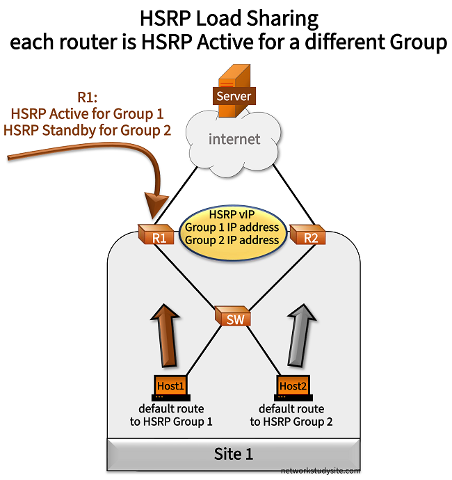
Hosts are assigned default routes that point to the HSRP virtual IP address of either Group 1 or Group 2. For example, Host1 uses the vIP of Group 1 (Active router R1), and Host2 uses the vIP of Group 2 (Active router R2). This is the concept behind Load Sharing with HSRP.
What is the difference between Load Sharing and Load Balancing?
HSRP can use Load Sharing to distribute traffic between a redundant pair of gateway routers. Hosts will always prefer the HSRP vIP configured as their default route, and the vIP will be mapped to a specific HSRP Active device. In other words, a group of hosts will prefer HSRP Active router R1, while another group of hosts will prefer HSRP Active router R2.
If suddenly Host1 starts to send much more data, or if multiple top-talker hosts are configured to use R1, then the traffic load will not be distributed evenly (this may even lead to congestion). On the other hand, Load Balancing involves a dynamic computational process of distributing traffic load between devices, and may rely on some form of Round Robin selection or hashing algorithm.
HSRP Load Sharing configuration - single VLAN
In the following example scenario, R1 and R2 are the gateway routers for Site 1. They use HSRP Groups to provide a redundant pair of default gateways for Host1 and Host2. Specifically, HSRP Load Sharing is configured which means that R1 is the HSRP Active router for Group 1, and R2 is Active for Group 2. This configuration is also called Multigroup HRSP (MHSRP).
The hosts are deliberately configured to choose one or the other HSRP Active router. Accordinly, Host1 has a default route pointing to the HSRP Group 1 virtual IP address, and Host2 has a default route pointing to the HSRP Group 2 vIP. Thus, the traffic load is shared between R1 and R2, but it is not necessarily balanced (depends on how much traffic is sent by each host).

Configuration:
R1
R1#show run int Gi0/0 | sec int
interface GigabitEthernet0/0
 description ** to SW **
 ip address 10.0.0.100 255.255.255.0
 standby 1 ip 10.0.0.1
 standby 1 timers msec 750 msec 1500
 standby 1 priority 150
 standby 1 preempt
 standby 2 ip 10.0.0.2
 standby 2 timers msec 750 msec 1500
 standby 2 priority 50
 standby 2 preempt
 duplex auto
 speed auto
 media-type rj45

R1#show run int Gi0/1 | sec int
interface GigabitEthernet0/1
 description ** to internet **
 ip address 172.16.1.1 255.255.255.252
 duplex auto
 speed auto
 media-type rj45

R1#show run | sec ^ip route
ip route 0.0.0.0 0.0.0.0 GigabitEthernet0/1 172.16.1.2
R2
R2#show run int Gi0/0 | sec int
interface GigabitEthernet0/0
 description ** to SW **
 ip address 10.0.0.200 255.255.255.0
 standby 1 ip 10.0.0.1
 standby 1 timers msec 750 msec 1500
 standby 1 priority 50
 standby 1 preempt
 standby 2 ip 10.0.0.2
 standby 2 timers msec 750 msec 1500
 standby 2 priority 150
 standby 2 preempt
 duplex auto
 speed auto
 media-type rj45

R2#show run int Gi0/1 | sec int
interface GigabitEthernet0/1
 description ** to internet **
 ip address 172.16.2.1 255.255.255.252
 duplex auto
 speed auto
 media-type rj45

R2#show run | sec ^ip route
ip route 0.0.0.0 0.0.0.0 GigabitEthernet0/1 172.16.2.2
SW
SW#show run int Gi0/0 | sec int
interface GigabitEthernet0/0
 description ** to R1 **
 switchport trunk allowed vlan 1
 switchport trunk encapsulation dot1q
 switchport mode trunk
 negotiation auto

SW#show run int Gi0/1 | sec int
interface GigabitEthernet0/1
 description ** to R2 **
 switchport trunk allowed vlan 1
 switchport trunk encapsulation dot1q
 switchport mode trunk
 negotiation auto

SW#show run int Gi0/2 | sec int
interface GigabitEthernet0/2
 description ** to Host1 **
 switchport mode access
 negotiation auto

SW#show run int Gi0/3 | sec int
interface GigabitEthernet0/3
 description ** to Host2 **
 switchport mode access
 negotiation auto
Host1
Host1#show run int Gi0/0 | sec int
interface GigabitEthernet0/0
 description ** to SW **
 ip address 10.0.0.10 255.255.255.0
 duplex auto
 speed auto
 media-type rj45

Host1#show run | sec ^ip route
ip route 0.0.0.0 0.0.0.0 GigabitEthernet0/0 10.0.0.1
Host2
Host2#show run int Gi0/0 | sec int
interface GigabitEthernet0/0
 description ** to SW **
 ip address 10.0.0.20 255.255.255.0
 duplex auto
 speed auto
 media-type rj45

Host2#show run | sec ^ip route
ip route 0.0.0.0 0.0.0.0 GigabitEthernet0/0 10.0.0.2
R1#show standby brief
                     P indicates configured to preempt.
                     |
Interface   Grp  Pri P State   Active          Standby         Virtual IP
Gi0/0       1    150 P Active  local           10.0.0.200      10.0.0.1     « R1 is HSRP Active router for Group 1
Gi0/0       2    50  P Standby 10.0.0.200      local           10.0.0.2


R2#show standby brief
                     P indicates configured to preempt.
                     |
Interface   Grp  Pri P State   Active          Standby         Virtual IP
Gi0/0       1    50  P Standby 10.0.0.100      local           10.0.0.1
Gi0/0       2    150 P Active  local           10.0.0.100      10.0.0.2     « R2 is HSRP Active router for Group 2


R2#show standby
GigabitEthernet0/0 - Group 1
  State is Standby
    1 state change, last state change 02:19:34
  Virtual IP address is 10.0.0.1
  Active virtual MAC address is 0000.0c07.ac01            « Virtual MAC address for HSRP Group 1
    Local virtual MAC address is 0000.0c07.ac01 (v1 default)
  Hello time 750 msec, hold time 1500 msec
    Next hello sent in 0.560 secs
  Preemption enabled
  Active router is 10.0.0.100, priority 150 (expires in 1.424 sec)
  Standby router is local
  Priority 50 (configured 50)
  Group name is "hsrp-Gi0/0-1" (default)
GigabitEthernet0/0 - Group 2
  State is Active
    1 state change, last state change 02:19:37
  Virtual IP address is 10.0.0.2
  Active virtual MAC address is 0000.0c07.ac02            « Virtual MAC address for HSRP Group 2
    Local virtual MAC address is 0000.0c07.ac02 (v1 default)
  Hello time 750 msec, hold time 1500 msec
    Next hello sent in 0.560 secs
  Preemption enabled
  Active router is local
  Standby router is 10.0.0.100, priority 50 (expires in 1.136 sec)
  Priority 150 (configured 150)
  Group name is "hsrp-Gi0/0-2" (default)


SW#show mac address-table
          Mac Address Table
-------------------------------------------

Vlan    Mac Address       Type        Ports
----    -----------       --------    -----
   1    0000.0c07.ac01    DYNAMIC     Gi0/0      « Switch learn HSRP Group 1 virtual MAC
   1    0000.0c07.ac02    DYNAMIC     Gi0/1      « HSRP Group 2 virtual MAC learned on different port
   1    5254.0000.61fe    DYNAMIC     Gi0/2
   1    5254.0006.ea91    DYNAMIC     Gi0/0
   1    5254.000a.49d6    DYNAMIC     Gi0/1
   1    5254.0011.fac1    DYNAMIC     Gi0/3
Total Mac Addresses for this criterion: 6


Host1#trace 172.16.0.1 probe 1
Type escape sequence to abort.
Tracing the route to 172.16.0.1
VRF info: (vrf in name/id, vrf out name/id)
  1 10.0.0.100 3 msec               « Host1 uses HSRP Group 1 Active router R1
  2 172.16.1.2 3 msec
  3 172.16.0.1 4 msecű


Host2#trace 172.16.0.1 probe 1
Type escape sequence to abort.
Tracing the route to 172.16.0.1
VRF info: (vrf in name/id, vrf out name/id)
  1 10.0.0.200 3 msec               « Host2 uses HSRP Group 2 Active router R2
  2 172.16.2.2 4 msec
  3 172.16.0.1 4 msec


R1#show int Gi0/0 | i 5 min
  5 minute input rate 11000 bits/sec, 12 packets/sec        « Host1 sends more traffic
  5 minute output rate 11000 bits/sec, 13 packets/sec


R2#show int Gi0/0 | i 5 min
  5 minute input rate 1000 bits/sec, 3 packets/sec
  5 minute output rate 1000 bits/sec, 2 packets/sec
As visible in the above router outputs, Host1 sends more traffic which leads to a higher load on R1. This is because Host1 always prefers to send traffic through R1, there is no load balancing but only load sharing. The benefit of such an HSRP design is that if R1 were to go offline, Host1 would immediately send traffic through R2 due to the HSRP automatic traffic switchover.
In a real-world production network there are many more details that go into such a solution to avoid potential traffic bottlenecks, an asymmetric return path or traffic blackholing. A common method is to deploy HSRP in combination with object tracking and IP SLA.
HSRP Load Sharing configuration - multiple VLANs
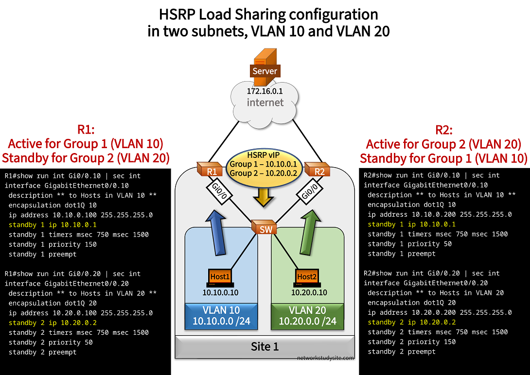
In this example topology Site 1 has two VLANs configured (10.10.0.0/24 and 10.20.0.0/24). Each VLAN uses a different HSRP Active router for traffic load sharing. The host in VLAN10 uses the HSRP vIP address for Group 1 (Active R1), and the host in VLAN20 uses the vIP for Group 2 (Active R2).
On R1 and R2 subinterfaces are configured for each VLAN, and HSRP is configured under each subinterface. This is how the traffic is shared per VLAN between R1 and R2. If either of the routers goes offline, HSRP failover will happen to the Standby router.
Configuration:
R1
R1#show run int Gi0/0.10 | sec int
interface GigabitEthernet0/0.10
 description ** to Hosts in VLAN 10 **
 encapsulation dot1Q 10
 ip address 10.10.0.100 255.255.255.0
 standby 1 ip 10.10.0.1
 standby 1 timers msec 750 msec 1500
 standby 1 priority 150
 standby 1 preempt

R1#show run int Gi0/0.20 | sec int
interface GigabitEthernet0/0.20
 description ** to Hosts in VLAN 20 **
 encapsulation dot1Q 20
 ip address 10.20.0.100 255.255.255.0
 standby 2 ip 10.20.0.2
 standby 2 timers msec 750 msec 1500
 standby 2 priority 50
 standby 2 preempt

R1#show run int Gi0/0 | sec int
interface GigabitEthernet0/0
 description ** to Hosts in Site 1 **
 no ip address
 duplex auto
 speed auto

R1#show run int Gi0/1 | sec int
interface GigabitEthernet0/1
 description ** to internet **
 ip address 172.16.1.1 255.255.255.252
 duplex auto
 speed auto
 media-type rj45

R1#show run | sec ^ip route
ip route 0.0.0.0 0.0.0.0 GigabitEthernet0/1 172.16.1.2
R2
R2#show run int Gi0/0.10 | sec int
interface GigabitEthernet0/0.10
 description ** to Hosts in VLAN 10 **
 encapsulation dot1Q 10
 ip address 10.10.0.200 255.255.255.0
 standby 1 ip 10.10.0.1
 standby 1 timers msec 750 msec 1500
 standby 1 priority 50
 standby 1 preempt

R2#show run int Gi0/0.20 | sec int
interface GigabitEthernet0/0.20
 description ** to Hosts in VLAN 20
 encapsulation dot1Q 20
 ip address 10.20.0.200 255.255.255.0
 standby 2 ip 10.20.0.2
 standby 2 timers msec 750 msec 1500
 standby 2 priority 150
 standby 2 preempt

R2#show run int Gi0/0 | sec int
interface GigabitEthernet0/0
 description ** to Hosts in Site 1 **
 no ip address
 duplex auto
 speed auto

R2#show run int Gi0/1 | sec int
interface GigabitEthernet0/1
 description ** to internet **
 ip address 172.16.2.1 255.255.255.252
 duplex auto
 speed auto
 media-type rj45

R2#show run | sec ^ip route
ip route 0.0.0.0 0.0.0.0 GigabitEthernet0/1 172.16.2.2
SW
SW#show run int Gi0/0 | sec int
interface GigabitEthernet0/0
 description ** to R1 **
 switchport trunk allowed vlan 10,20
 switchport trunk encapsulation dot1q
 switchport mode trunk
 negotiation auto

SW#show run int Gi0/1 | sec int
interface GigabitEthernet0/1
 description ** to R2 **
 switchport trunk allowed vlan 10,20
 switchport trunk encapsulation dot1q
 switchport mode trunk
 negotiation auto

SW#show run int Gi0/2 | sec int
interface GigabitEthernet0/2
 description ** to Host1 **
 switchport access vlan 10
 switchport mode access
 negotiation auto

SW#show run int Gi0/3 | sec int
interface GigabitEthernet0/3
 description ** to Host2 **
 switchport access vlan 20
 switchport mode access
 negotiation auto
Host1
Host1#show run int Gi0/0 | sec int
interface GigabitEthernet0/0
 description ** to SW **
 ip address 10.10.0.10 255.255.255.0
 duplex auto
 speed auto
 media-type rj45

Host1#show run | sec ^ip route
ip route 0.0.0.0 0.0.0.0 GigabitEthernet0/0 10.10.0.1
Host2
Host2#show run int Gi0/0 | sec int
interface GigabitEthernet0/0
 description ** to SW **
 ip address 10.20.0.10 255.255.255.0
 duplex auto
 speed auto
 media-type rj45

Host2#show run | sec ^ip route
ip route 0.0.0.0 0.0.0.0 GigabitEthernet0/0 10.20.0.2
R1#show standby brief
                     P indicates configured to preempt.
                     |
Interface   Grp  Pri P State   Active          Standby         Virtual IP
Gi0/0.10    1    150 P Active  local           10.10.0.200     10.10.0.1         « R1 is HSRP Active router for Group 1 (VLAN 10)
Gi0/0.20    2    50  P Standby 10.20.0.200     local           10.20.0.2


R2#show standby brief
                     P indicates configured to preempt.
                     |
Interface   Grp  Pri P State   Active          Standby         Virtual IP
Gi0/0.10    1    50  P Standby 10.10.0.100     local           10.10.0.1
Gi0/0.20    2    150 P Active  local           10.20.0.100     10.20.0.2         « R2 is HSRP Active router for Group 2 (VLAN 20)


R1#show arp
Protocol  Address          Age (min)  Hardware Addr   Type   Interface
Internet  10.10.0.1               -   0000.0c07.ac01  ARPA   GigabitEthernet0/0.10     « HSRP Group 1 vIP and virtual MAC
Internet  10.10.0.10             66   5254.0000.61fe  ARPA   GigabitEthernet0/0.10
Internet  10.10.0.100             -   5254.0006.ea91  ARPA   GigabitEthernet0/0.10
Internet  10.20.0.10             65   5254.0011.fac1  ARPA   GigabitEthernet0/0.20
Internet  10.20.0.100             -   5254.0006.ea91  ARPA   GigabitEthernet0/0.20
Internet  172.16.1.1              -   5254.000a.9748  ARPA   GigabitEthernet0/1
Internet  172.16.1.2            239   5254.000b.461f  ARPA   GigabitEthernet0/1


R2#show arp
Protocol  Address          Age (min)  Hardware Addr   Type   Interface
Internet  10.10.0.10             67   5254.0000.61fe  ARPA   GigabitEthernet0/0.10
Internet  10.10.0.200             -   5254.000a.49d6  ARPA   GigabitEthernet0/0.10
Internet  10.20.0.2               -   0000.0c07.ac02  ARPA   GigabitEthernet0/0.20     « HSRP Group 2 vIP and virtual MAC
Internet  10.20.0.10             65   5254.0011.fac1  ARPA   GigabitEthernet0/0.20
Internet  10.20.0.200             -   5254.000a.49d6  ARPA   GigabitEthernet0/0.20
Internet  172.16.2.1              -   5254.0003.9410  ARPA   GigabitEthernet0/1
Internet  172.16.2.2            239   5254.0013.c3ee  ARPA   GigabitEthernet0/1


Host1#trace 172.16.0.1 probe 1
Type escape sequence to abort.
Tracing the route to 172.16.0.1
VRF info: (vrf in name/id, vrf out name/id)
  1 10.10.0.100 3 msec               « Host1 in VLAN 10 sends traffic through R1
  2 172.16.1.2 3 msec
  3 172.16.0.1 3 msec


Host2#trace 172.16.0.1 probe 1
Type escape sequence to abort.
Tracing the route to 172.16.0.1
VRF info: (vrf in name/id, vrf out name/id)
  1 10.20.0.200 3 msec               « Host2 in VLAN 20 sends traffic through R2
  2 172.16.2.2 3 msec
  3 172.16.0.1 4 msec