How a Router-on-a-Stick Design Can Benefit Your Network
Table of Contents
- What is the purpose of a router-on-a-stick? ‹
- What is a disadvantage of router-on-a-stick? ‹
- How to configure a router-on-a-stick? ‹
- Router on a stick with VRF configuration ‹
- Download section ‹
What is the purpose of a router-on-a-stick?
A router on a stick provides inter-VLAN routing with a simple design. Namely, a single router is required with a LAN-facing physical interface connected to a switch through a trunk port. However, the router has multiple logical subinterfaces configured in each individual VLAN. The logical interfaces have IP addresses which can become the default gateway for hosts residing in that particular VLAN.
What is a disadvantage of router-on-a-stick?
There are several disadvantages of a router on a stick design.
- the physical link on the router is a single point of failure for all configured VLANs
- the physical link on the router can become overloaded with data traffic, and this leads to network conjestion
A router on a stick design is well suited for smaller locations with a single gateway router, but may not be the best option for larger networks. As a scalable and common alternative, a Switched Virtual Interface (SVI) can be configured on a Layer-3 switch.
How to configure a router-on-a-stick?
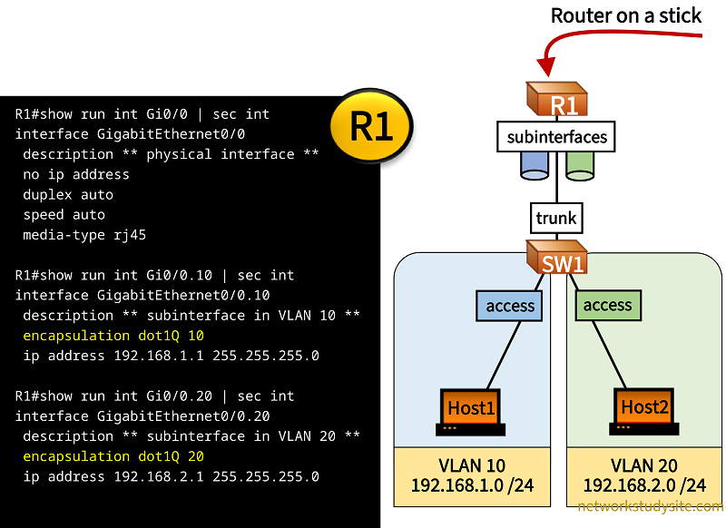
The following example topology shows a router on a stick design. Router R1 is connected to switch SW1 on a single physical link, carrying traffic for VLAN 10 and 20. On the switch a trunk port is configured towards R1. Meanwhile on R1 subinterfaces are configured in each individual VLAN, and these subinterfaces become the default gateway for Host1 and Host2.
Thus, R1 can route traffic between two VLANs using a single physical link, but two logical Layer-3 interfaces.
Configuration:
R1
R1#show run int Gi0/0 | sec int
interface GigabitEthernet0/0
 description ** physical interface **
 no ip address
 duplex auto
 speed auto
 media-type rj45

R1#show run int Gi0/0.10 | sec int
interface GigabitEthernet0/0.10
 description ** subinterface in VLAN 10 **
 encapsulation dot1Q 10
 ip address 192.168.1.1 255.255.255.0

R1#show run int Gi0/0.20 | sec int
interface GigabitEthernet0/0.20
 description ** subinterface in VLAN 20 **
 encapsulation dot1Q 20
 ip address 192.168.2.1 255.255.255.0
SW1
SW1#show run int Gi0/0 | sec int
interface GigabitEthernet0/0
 description ** trunk to R1 **
 switchport trunk encapsulation dot1q
 switchport mode trunk
 negotiation auto

SW1#show run int Gi0/1 | sec int
interface GigabitEthernet0/1
 description ** access port to Host1 **
 switchport access vlan 10
 switchport mode access
 negotiation auto

SW1#show run int Gi0/2 | sec int
interface GigabitEthernet0/2
 description ** access port to Host2 **
 switchport access vlan 20
 switchport mode access
 negotiation auto
Host1:~$ ping 192.168.2.2 -c 5
PING 192.168.2.2 (192.168.2.2): 56 data bytes
64 bytes from 192.168.2.2: seq=0 ttl=42 time=2.629 ms
64 bytes from 192.168.2.2: seq=1 ttl=42 time=2.693 ms
64 bytes from 192.168.2.2: seq=2 ttl=42 time=2.762 ms
64 bytes from 192.168.2.2: seq=3 ttl=42 time=2.693 ms
64 bytes from 192.168.2.2: seq=4 ttl=42 time=2.796 ms

--- 192.168.2.2 ping statistics ---
5 packets transmitted, 5 packets received, 0% packet loss        « Host1 can ping Host2
round-trip min/avg/max = 2.629/2.714/2.796 ms


R1#ping 192.168.1.2
Type escape sequence to abort.
Sending 5, 100-byte ICMP Echos to 192.168.1.2, timeout is 2 seconds:
!!!!!
Success rate is 100 percent (5/5), round-trip min/avg/max = 2/2/3 ms          « R1 can ping Host1


R1#ping 192.168.2.2
Type escape sequence to abort.
Sending 5, 100-byte ICMP Echos to 192.168.2.2, timeout is 2 seconds:
!!!!!
Success rate is 100 percent (5/5), round-trip min/avg/max = 1/2/3 ms         « R1 can ping Host2
Router on a stick with VRF configuration
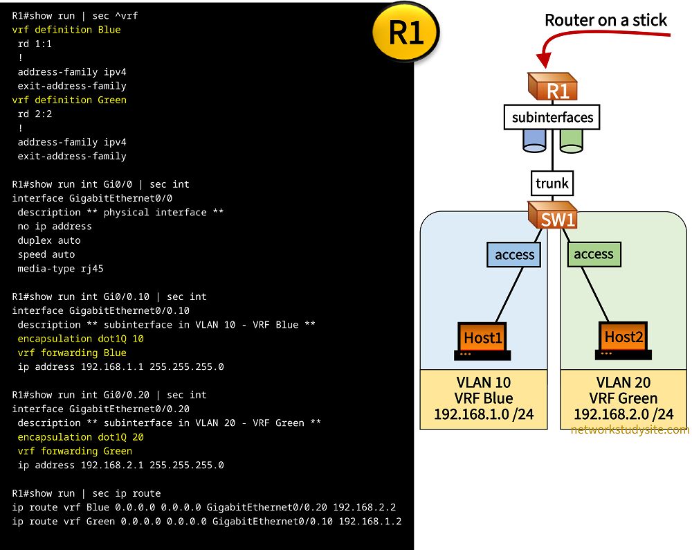
In the following example topology, a router on a stick is configured with VLAN 10 and 20, and with VRF Blue and Green. The subinterfaces on R1 are routed Layer-3 interfaces that are each configured with a VLAN and VRF. The subinterfaces on R1 act as the default gateway for Host1 and Host2, and are connected through switch SW1 using a trunk port and access ports in their respective VLANs.
As a result, network segmentation happens on OSI Layer-2 because the VLANs create independent broadcast domains. However, the network is also segmented at OSI Layer-3 because there are independent and separate routing tables for VRF Blue and VRF Green. To enable communication between Host1 and Host2, static routes are added in each VRF routing table.
Configuration:
R1
R1#show run | sec ^vrf
vrf definition Blue
 rd 1:1
 !
 address-family ipv4
 exit-address-family
vrf definition Green
 rd 2:2
 !
 address-family ipv4
 exit-address-family

R1#show run int Gi0/0 | sec int
interface GigabitEthernet0/0
 description ** physical interface **
 no ip address
 duplex auto
 speed auto
 media-type rj45

R1#show run int Gi0/0.10 | sec int
interface GigabitEthernet0/0.10
 description ** subinterface in VLAN 10 - VRF Blue **
 encapsulation dot1Q 10
 vrf forwarding Blue
 ip address 192.168.1.1 255.255.255.0

R1#show run int Gi0/0.20 | sec int
interface GigabitEthernet0/0.20
 description ** subinterface in VLAN 20 - VRF Green **
 encapsulation dot1Q 20
 vrf forwarding Green
 ip address 192.168.2.1 255.255.255.0

R1#show run | sec ip route
ip route vrf Blue 0.0.0.0 0.0.0.0 GigabitEthernet0/0.20 192.168.2.2
ip route vrf Green 0.0.0.0 0.0.0.0 GigabitEthernet0/0.10 192.168.1.2
SW1
SW1#show run int Gi0/0 | sec int
interface GigabitEthernet0/0
 description ** trunk to R1 **
 switchport trunk encapsulation dot1q
 switchport mode trunk
 negotiation auto

SW1#show run int Gi0/1 | sec int
interface GigabitEthernet0/1
 description ** access port to Host1 **
 switchport access vlan 10
 switchport mode access
 negotiation auto

SW1#show run int Gi0/2 | sec int
interface GigabitEthernet0/2
 description ** access port to Host2 **
 switchport access vlan 20
 switchport mode access
 negotiation auto
Host1:~$ ping 192.168.2.2 -c 5
PING 192.168.2.2 (192.168.2.2): 56 data bytes
64 bytes from 192.168.2.2: seq=0 ttl=42 time=2.803 ms
64 bytes from 192.168.2.2: seq=1 ttl=42 time=2.961 ms
64 bytes from 192.168.2.2: seq=2 ttl=42 time=3.432 ms
64 bytes from 192.168.2.2: seq=3 ttl=42 time=3.547 ms
64 bytes from 192.168.2.2: seq=4 ttl=42 time=3.110 ms

--- 192.168.2.2 ping statistics ---
5 packets transmitted, 5 packets received, 0% packet loss         « Host1 can ping Host2
round-trip min/avg/max = 2.803/3.170/3.547 ms


R1#ping vrf Blue 192.168.1.2
Type escape sequence to abort.
Sending 5, 100-byte ICMP Echos to 192.168.1.2, timeout is 2 seconds:
!!!!!
Success rate is 100 percent (5/5), round-trip min/avg/max = 2/2/2 ms            « R1 can ping Host1


R1#ping vrf Green 192.168.2.2
Type escape sequence to abort.
Sending 5, 100-byte ICMP Echos to 192.168.2.2, timeout is 2 seconds:
!!!!!
Success rate is 100 percent (5/5), round-trip min/avg/max = 2/2/2 ms            « R1 can ping Host2