Multiple Spanning Tree Protocol (MST) Explained
- What is Multiple Spanning Tree Protocol (MSTP)? ‹
- How to configure MSTP? ‹
- Load balancing traffic with multiple MST Instances ‹
- Packet capture of MST BPDU with IST, MST Extension and MRecord ‹
- MST and RPVST interoperation ‹
- Download section ‹
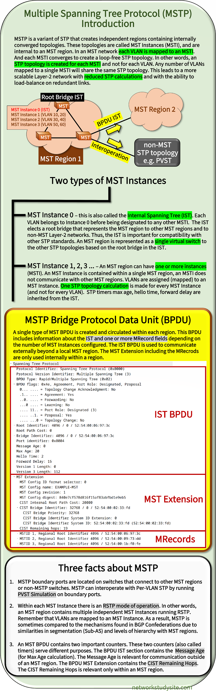
What is Multiple Spanning Tree Protocol (MSTP)?
The following image is a summary about the main features of MST.
How to configure MSTP?
In the following example topology a Multiple Spanning-Tree (MST) region is configured with the single MST Instance (MSTI) 1. VLAN 10 and VLAN 20 are mapped to MSTI 1, therefore these two VLANs have identical STP topologies calculated in the MST region. SW1 is configured as the root bridge, and SW2 is the secondary root bridge. For inter-VLAN communication, SW1 has Switch Virtual Interface (SVI) configured.
Furthermore, SW4 and SW5 have the MST interface cost adjusted to ensure a predictable forwarding path towards the root bridge. Note that the MST cost is assigned per MSTI. This means, the configured MST interface cost will influence the forwarding path for traffic in VLAN 10 and in VLAN 20 simultaneously. The pathcost method long is configured throghout the topology.

Configuration:
SW1
SW1#show run | sec ^spanning
spanning-tree mode mst
spanning-tree extend system-id
spanning-tree pathcost method long
spanning-tree mst configuration
 name EXAMPLE-MST
 revision 1
 instance 1 vlan 10, 20
spanning-tree mst 0-1 priority 4096

SW1#show run int Gi0/0 | sec int
interface GigabitEthernet0/0
 description ** to SW2 **
 switchport trunk allowed vlan 1,10,20
 switchport trunk encapsulation dot1q
 negotiation auto

SW1#show run int Gi0/1 | sec int
interface GigabitEthernet0/1
 description ** to SW3 **
 switchport trunk allowed vlan 1,10,20
 switchport trunk encapsulation dot1q
 negotiation auto

SW1#show run int vlan 10 | sec int
interface Vlan10
 description ** SVI for Host1 in VLAN 10 **
 ip address 192.168.1.2 255.255.255.0

SW1#show run int vlan 20 | sec int
interface Vlan20
 description ** SVI for Host2 in VLAN 20 **
 ip address 192.168.2.2 255.255.255.0
SW2
SW2#show run | sec ^spanning
spanning-tree mode mst
spanning-tree extend system-id
spanning-tree pathcost method long
spanning-tree mst configuration
 name EXAMPLE-MST
 revision 1
 instance 1 vlan 10, 20
spanning-tree mst 0-1 priority 8192

SW2#show run int Gi0/0 | sec int
interface GigabitEthernet0/0
 description ** to SW4 **
 switchport trunk allowed vlan 1,10,20
 switchport trunk encapsulation dot1q
 switchport mode trunk
 negotiation auto

SW2#show run int Gi0/1 | sec int
interface GigabitEthernet0/1
 description ** to SW5 **
 switchport trunk allowed vlan 1,10,20
 switchport trunk encapsulation dot1q
 switchport mode trunk
 negotiation auto

SW2#show run int Gi0/2 | sec int
interface GigabitEthernet0/2
 description ** to SW3 **
 switchport trunk allowed vlan 1,10,20
 switchport trunk encapsulation dot1q
 switchport mode trunk
 negotiation auto
SW3
SW3#show run | sec ^spanning
spanning-tree mode mst
spanning-tree extend system-id
spanning-tree pathcost method long
spanning-tree mst configuration
 name EXAMPLE-MST
 revision 1
 instance 1 vlan 10, 20
spanning-tree mst 0-1 priority 16384

SW3#show run int Gi0/0 | sec int
interface GigabitEthernet0/0
 description ** to SW4 **
 switchport trunk allowed vlan 1,10,20
 switchport trunk encapsulation dot1q
 switchport mode trunk
 negotiation auto

SW3#show run int Gi0/1 | sec int
interface GigabitEthernet0/1
 description ** to SW5 **
 switchport trunk allowed vlan 1,10,20
 switchport trunk encapsulation dot1q
 switchport mode trunk
 negotiation auto

SW3#show run int Gi0/2 | sec int
interface GigabitEthernet0/2
 description ** to SW2 **
 switchport trunk allowed vlan 1,10,20
 switchport trunk encapsulation dot1q
 switchport mode trunk
 negotiation auto
SW4
SW4#show run | sec ^spanning
spanning-tree mode mst
spanning-tree extend system-id
spanning-tree pathcost method long
spanning-tree mst configuration
 name EXAMPLE-MST
 revision 1
 instance 1 vlan 10, 20

SW4#show run int Gi0/0 | sec int
interface GigabitEthernet0/0
 description ** to Host1 **
 switchport access vlan 10
 switchport mode access
 negotiation auto

SW4#show run int Gi0/1 | sec int
interface GigabitEthernet0/1
 description ** to SW2 **
 switchport trunk allowed vlan 1,10,20
 switchport trunk encapsulation dot1q
 switchport mode trunk
 negotiation auto
 spanning-tree mst 0-1 cost 50

SW4#show run int Gi0/2 | sec int
interface GigabitEthernet0/2
 description ** to SW3 **
 switchport trunk allowed vlan 1,10,20
 switchport trunk encapsulation dot1q
 switchport mode trunk
 negotiation auto
 spanning-tree mst 0-1 cost 100
SW5
SW5#show run | sec ^spanning
spanning-tree mode mst
spanning-tree extend system-id
spanning-tree pathcost method long
spanning-tree mst configuration
 name EXAMPLE-MST
 revision 1
 instance 1 vlan 10, 20

SW5#show run int Gi0/0 | sec int
interface GigabitEthernet0/0
 description ** to Host2 **
 switchport access vlan 20
 switchport mode access
 negotiation auto

SW5#show run int Gi0/1 | sec int
interface GigabitEthernet0/1
 description ** to SW2 **
 switchport trunk allowed vlan 1,10,20
 switchport trunk encapsulation dot1q
 switchport mode trunk
 negotiation auto
 spanning-tree mst 0-1 cost 50

SW5#show run int Gi0/2 | sec int
interface GigabitEthernet0/2
 description ** to SW3 **
 switchport trunk allowed vlan 1,10,20
 switchport trunk encapsulation dot1q
 switchport mode trunk
 negotiation auto
 spanning-tree mst 0-1 cost 100
SW1#show spanning-tree mst 1

##### MST1    vlans mapped:   10,20
Bridge        address 5254.000a.e887  priority      4097  (4096 sysid 1)          « Bridge Priority on SW1
Root          this switch for MST1                                                « SW1 is the root bridge for MST Instance 1

Interface        Role Sts Cost      Prio.Nbr Type
---------------- ---- --- --------- -------- --------------------------------
Gi0/0            Desg FWD 20000     128.1    P2p
Gi0/1            Desg FWD 20000     128.2    P2p


SW1#show spanning-tree mst 0

##### MST0    vlans mapped:   1-9,11-19,21-4094
Bridge        address 5254.000a.e887  priority      4096  (4096 sysid 0)
Root          this switch for the CIST                                            « SW1 is also the root bridge for the MST CIST (Instance 0)
Operational   hello time 2 , forward delay 15, max age 20, txholdcount 6
Configured    hello time 2 , forward delay 15, max age 20, max hops    20

Interface        Role Sts Cost      Prio.Nbr Type
---------------- ---- --- --------- -------- --------------------------------
Gi0/0            Desg FWD 20000     128.1    P2p
Gi0/1            Desg FWD 20000     128.2    P2p
Gi0/2            Desg FWD 20000     128.3    P2p
Gi0/3            Desg FWD 20000     128.4    P2p


SW1#show spanning-tree mst configuration
Name      [EXAMPLE-MST]
Revision  1     Instances configured 2                                           « Instance 0, and Instance 1 are in use

Instance  Vlans mapped
--------  ---------------------------------------------------------------------
0         1-9,11-19,21-4094                                                      « All VLANs are mapped to Instance 0 by default
1         10,20
-------------------------------------------------------------------------------


SW1#show spanning-tree mst interface Gi0/0

GigabitEthernet0/0 of MST0 is designated forwarding
Portfast : no             (default)        port guard : none        (default)
Link type: point-to-point (auto)           bpdu filter: disable     (default)
Boundary : internal                        bpdu guard : disable     (default)     « Boundary port connects to other MST region or non-MST switch
PVST Sim : enable         (default)
Bpdus sent 5574, received 44

Instance Role Sts Cost      Prio.Nbr Vlans mapped
-------- ---- --- --------- -------- -------------------------------
0        Desg FWD 20000     128.1    1-9,11-19,21-4094
1        Desg FWD 20000     128.1    10,20


SW2#show spanning-tree mst 1

##### MST1    vlans mapped:   10,20
Bridge        address 5254.000f.3689  priority      8193  (8192 sysid 1)
Root          address 5254.000a.e887  priority      4097  (4096 sysid 1)
              port    Gi0/3           cost          20000     rem hops 19           « The hop count is part of the MST Extension and is decreased

Interface        Role Sts Cost      Prio.Nbr Type
---------------- ---- --- --------- -------- --------------------------------
Gi0/0            Desg FWD 20000     128.1    P2p
Gi0/1            Desg FWD 20000     128.2    P2p
Gi0/2            Desg FWD 20000     128.3    P2p
Gi0/3            Root FWD 20000     128.4    P2p


SW4#show spanning-tree mst 1

##### MST1    vlans mapped:   10,20
Bridge        address 5254.000d.f047  priority      32769 (32768 sysid 1)
Root          address 5254.000f.3689  priority      8193  (8192 sysid 1)
              port    Gi0/1           cost          50        rem hops 19

Interface        Role Sts Cost      Prio.Nbr Type
---------------- ---- --- --------- -------- --------------------------------
Gi0/0            Desg FWD 20000     128.1    P2p
Gi0/1            Root FWD 50        128.2    P2p         « MST cost is adjusted
Gi0/2            Desg FWD 100       128.3    P2p


Host1:~$ ping 192.168.2.1 -c 5
PING 192.168.2.1 (192.168.2.1): 56 data bytes
64 bytes from 192.168.2.1: seq=0 ttl=42 time=7.551 ms
64 bytes from 192.168.2.1: seq=1 ttl=42 time=5.957 ms
64 bytes from 192.168.2.1: seq=2 ttl=42 time=5.813 ms
64 bytes from 192.168.2.1: seq=3 ttl=42 time=5.363 ms
64 bytes from 192.168.2.1: seq=4 ttl=42 time=6.276 ms

--- 192.168.2.1 ping statistics ---
5 packets transmitted, 5 packets received, 0% packet loss                          « Host1 (VLAN 10) can reach Host2 (VlAN 20)
round-trip min/avg/max = 5.363/6.192/7.551 ms


Host1:~$ traceroute 192.168.2.1 -q 1 -n
traceroute to 192.168.2.1 (192.168.2.1), 30 hops max, 46 byte packets
 1  192.168.1.2  3.162 ms                                                           « IP address of the SVI interface on SW1
 2  192.168.2.1  5.992 ms
As visible in the above outputs the MST Instance 0 (CIST) contains all the VLANs by default unless they are mapped to another MSTI. This can be accomplished with the commands shown in the following output from SW1 where all the mappable VLANs are assigned to MST Instance 1, including the native VLAN 1.
SW1>
SW1>enable
SW1#configure terminal
Enter configuration commands, one per line.  End with CNTL/Z.
SW1(config)#spanning-tree mst configuration
SW1(config-mst)#instance 1 vlan 1-9,11-19,21-4094
SW1(config-mst)#exit
SW1(config)#exit
SW1#


SW1#show spanning-tree mst configuration
Name      [EXAMPLE-MST]
Revision  1     Instances configured 2

Instance  Vlans mapped
--------  ---------------------------------------------------------------------
0         none
1         1-4094
-------------------------------------------------------------------------------
Load balancing traffic with multiple MST Instances
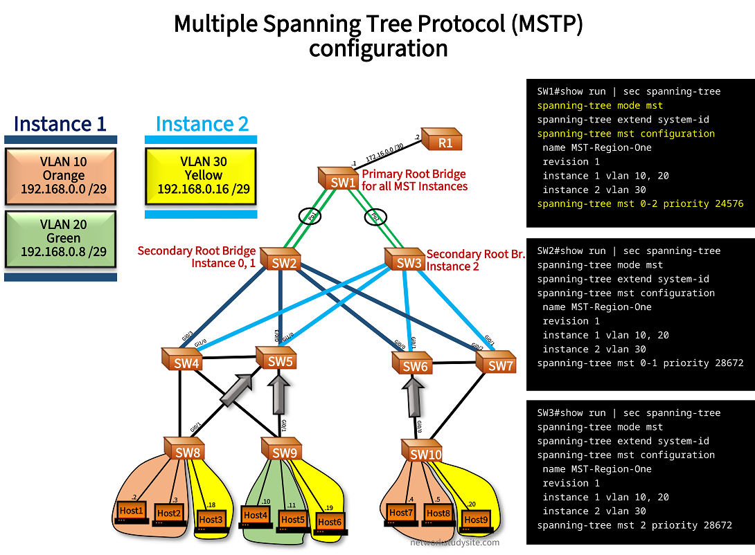
In the below sample topology, all switches belong to the same MST region, called "MST-Region-One" which contains MST Instance (MSTI) 0, 1, and 2. This creates three separate STP topologies which are called instances (MSTI) in Multiple Spanning Tree and are detailed below:
- MSTI 0 is the IST.
- MSTI 1 contains VLAN 10, 20.
- MSTI 2 contains VLAN 30.
Configuration:
SW1
SW1#show run | sec spanning-tree
spanning-tree mode mst
spanning-tree extend system-id
spanning-tree mst configuration
 name MST-Region-One
 revision 1
 instance 1 vlan 10, 20
 instance 2 vlan 30
spanning-tree mst 0-2 priority 24576
SW2
SW2#show run | sec spanning-tree
spanning-tree mode mst
spanning-tree extend system-id
spanning-tree mst configuration
 name MST-Region-One
 revision 1
 instance 1 vlan 10, 20
 instance 2 vlan 30
spanning-tree mst 0-1 priority 28672
SW3
SW3#show run | sec spanning-tree
spanning-tree mode mst
spanning-tree extend system-id
spanning-tree mst configuration
 name MST-Region-One
 revision 1
 instance 1 vlan 10, 20
 instance 2 vlan 30
spanning-tree mst 2 priority 28672
As a result, for VLAN 10 and 20 there is only a single STP topology calculated under the MSTI 1, which uses the secondary root bridge SW2. Meanwhile, for MSTI 2 the secondary root bridge is SW3. Two switches belong to the same MST region if the MST Name, Revision number, MST Instances including the mapped VLANs match.
SW2#show spanning-tree bridge protocol
MST0             mstp                   « MSTP is being used
MST1             mstp
MST2             mstp


SW2#show spanning-tree mst configuration
Name      [MST-Region-One]
Revision  1     Instances configured 3

Instance  Vlans mapped
--------  ---------------------------------------------------------------------
0         1-9,11-19,21-29,31-4094
1         10,20
2         30
-------------------------------------------------------------------------------


SW2#show spanning-tree mst configuration digest
Name      [MST-Region-One]
Revision  1     Instances configured 3
Digest          0xAE42EDCCE65E40889987FF15EC6BF844   « Matching digest values between switches to be part in same MST region
Pre-std Digest  0x91165CA50D86606102493C71983754EC


SW2#show spanning-tree bridge priority
MST0             28672
MST1             28673
MST2             32770


SW2#show spanning-tree bridge id
MST0             7000.5254.0016.a282
MST1             7001.5254.0016.a282
MST2             8002.5254.0016.a282


SW2#show spanning-tree root cost
MST0             0
MST1             10000   « Pathcost method long is used, Port-channel interface cost 10000
MST2             10000


SW2#show spanning-tree root port
MST0             Port-channel1
MST1             Port-channel1
MST2             Port-channel1


SW5#show spanning-tree root cost
MST0             0
MST1             30000     « Gigabit Ethernet cost 20000 + Port-channel iface 10000
MST2             30000


SW2#show spanning-tree root address
MST0             5254.000d.955a
MST1             5254.000d.955a
MST2             5254.000d.955a
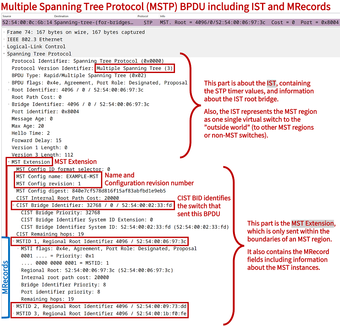
Packet capture of MST BPDU with IST, MST Extension and MRecord
A capture of a BPDU between SW3 - SW6 confirms details about MSTP. The IST is highlighted, and Max Age, Hellow Time, and Forward Delay are visible in the packet capture. The values are inherited by the different MST Instances that are contained in the MRecord fields. Two MRecords are included in this BPDU, one MRecord for each MST Instance.
MST and RPVST interoperation
In the following example the LAN environment has two segments:
- • an MST region
- • and access switches using Rapid-PVST
The two STP standards interoperate. The MST region is represented as a single virtual switch towards the switches using RPVST. The MST boundary ports send BPDUs to the switches which are using RPVST. BPDUs are sent by the MST boundary ports for every VLAN separately, and advertising the values of the IST. The IST represents the entire MST region as a single virtual switch.
Ports on MSTP switches that connect the MSTP region to the switches running RPVST are called boundary ports. Two example boundary ports are on SW5 interfaces Gi0/0 and Gi0/1, these are highlighted in the following topology.

Configuration:
SW1
SW1#show run | sec spanning-tree
spanning-tree mode mst
spanning-tree extend system-id
spanning-tree mst configuration
 name MST-Region-One
 revision 1
 instance 1 vlan 10, 20
 instance 2 vlan 30
spanning-tree mst 0 priority 8192
spanning-tree mst 1 priority 12288
spanning-tree mst 2 priority 16384
SW2
SW2#show run | sec spanning-tree
spanning-tree mode mst
spanning-tree extend system-id
spanning-tree mst configuration
 name MST-Region-One
 revision 1
 instance 1 vlan 10, 20
 instance 2 vlan 30
spanning-tree mst 0-1 priority 28672
SW3
SW3#show run | sec spanning-tree
spanning-tree mode mst
spanning-tree extend system-id
spanning-tree mst configuration
 name MST-Region-One
 revision 1
 instance 1 vlan 10, 20
 instance 2 vlan 30
spanning-tree mst 2 priority 28672
SW5#show spanning-tree

MST0
  Spanning tree enabled protocol mstp
  Root ID    Priority    8192
             Address     5254.000d.955a   « Root bridge is SW1
             Cost        0
             Port        4 (GigabitEthernet0/3)
             Hello Time   2 sec  Max Age 20 sec  Forward Delay 15 sec

  Bridge ID  Priority    32768  (priority 32768 sys-id-ext 0)
             Address     5254.0001.aecc
             Hello Time   2 sec  Max Age 20 sec  Forward Delay 15 sec

Interface           Role Sts Cost      Prio.Nbr Type
------------------- ---- --- --------- -------- --------------------------------
Gi0/0               Desg FWD 20000     128.1    P2p Bound(PVST)   « Boundary port
Gi0/1               Desg FWD 20000     128.2    P2p Bound(PVST)
Gi0/2               Altn BLK 20000     128.3    P2p
Gi0/3               Root FWD 20000     128.4    P2p
Gi1/0               Altn BLK 20000     128.5    P2p
Gi1/1               Desg FWD 20000     128.6    P2p
Gi1/2               Desg FWD 20000     128.7    P2p
Gi1/3               Desg FWD 20000     128.8    P2p


SW5#show spanning-tree interface Gi0/0

Mst Instance        Role Sts Cost      Prio.Nbr Type
------------------- ---- --- --------- -------- --------------------------------
MST0                Desg FWD 20000     128.1    P2p Bound(PVST)    « Gi0/0 is a boundary port for all MST instances
MST1                Desg FWD 20000     128.1    P2p Bound(PVST)
MST2                Desg FWD 20000     128.1    P2p Bound(PVST)


SW5#show spanning-tree interface Gi0/0 detail | sec MST0
 Port 1 (GigabitEthernet0/0) of MST0 is designated forwarding
   Port path cost 20000, Port priority 128, Port Identifier 128.1.
   Designated root has priority 8192, address 5254.000d.955a
   Designated bridge has priority 32768, address 5254.0001.aecc
   Designated port id is 128.1, designated path cost 0
   Timers: message age 0, forward delay 0, hold 0
   Number of transitions to forwarding state: 7
   Link type is point-to-point by default, Boundary PVST
   PVST Simulation is enabled by default                    « PVST Simulation on boundary port
   BPDU: sent 6887, received 65


SW9#show run | sec spanning-tree mode
spanning-tree mode rapid-pvst « Spanning-tree mode RPVST


SW9#show spanning-tree | i protocol
  Spanning tree enabled protocol rstp
  Spanning tree enabled protocol rstp
  Spanning tree enabled protocol rstp